Method and system for pre-atomizing catalytic feed oil

A technology of feed oil and feed port, applied in chemical instruments and methods, catalytic cracking, feed devices, etc., can solve the problem of poor atomization effect of catalytic feed oil

Active Publication Date: 2022-08-05
湖南长科诚享石化科技有限公司
View PDF10 Cites 0 Cited by
  • Summary
  • Abstract
  • Description
  • Claims
  • Application Information

AI Technical Summary

Problems solved by technology

[0012] The purpose of the present invention is to overcome the defect that t

Method used


Image

  • Method and system for pre-atomizing catalytic feed oil
  • Method and system for pre-atomizing catalytic feed oil
  • Method and system for pre-atomizing catalytic feed oil

Examples


Embodiment 1

[0096] In the present embodiment, the pre-atomization of the catalytic feed oil is carried out according to the following steps:

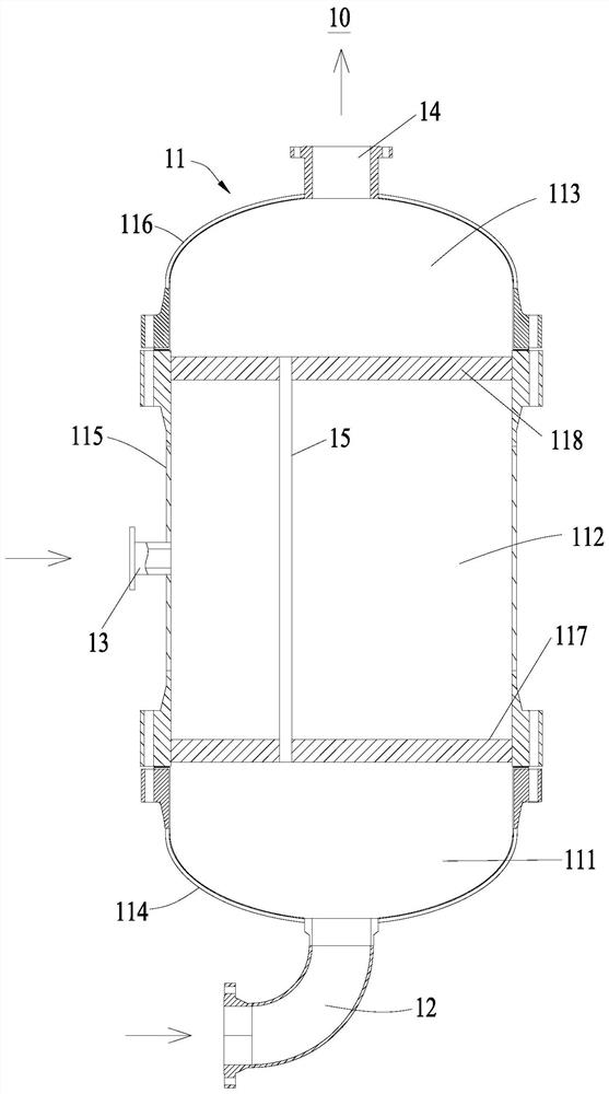
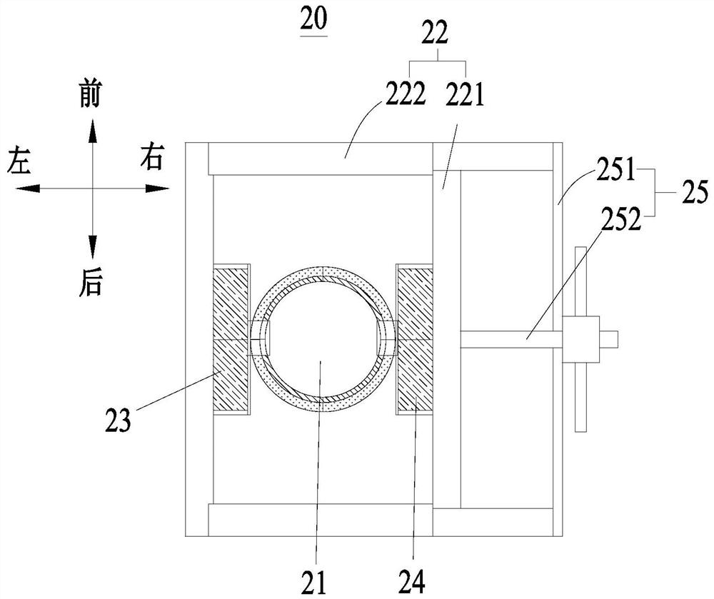
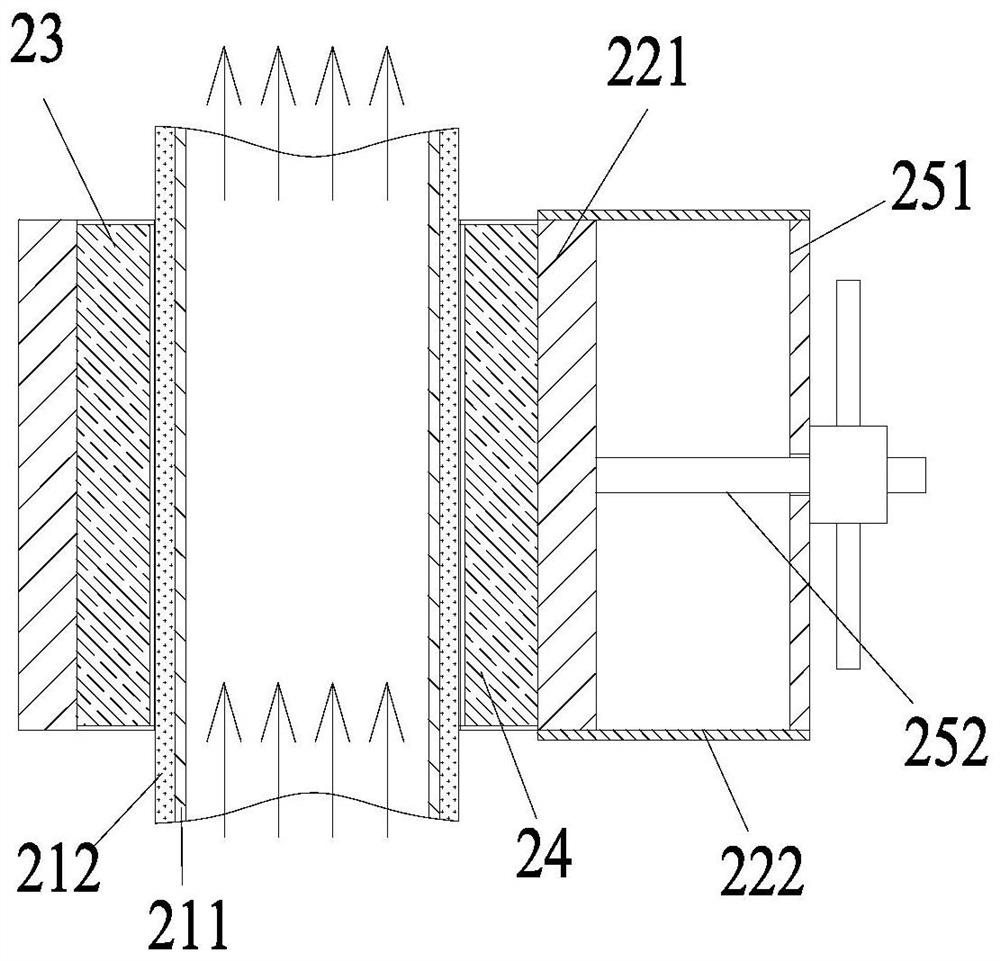
[0097] (1) The atomized gas is introduced into the middle cavity of the micro-interface treatment tank through the atomized gas feed port, and the atomized gas enters the micro-interface catheter through the air hole on the pipe wall of the micro-interface catheter for dispersion. , to obtain microbubbles, and the dispersion conditions include: the temperature is 250 ° C, the pressure is 1.0 MPa, the feed flow of the atomizing gas is 130 kg / h; the atomizing gas is superheated steam;

[0098] (2) The catalytic feed oil is introduced into the bottom cavity of the micro-interface treatment tank through the catalytic oil feed port, and the catalytic feed oil enters the micro-interface conduit through the bottom inlet of the micro-interface conduit, and is combined with the micro-interface conduit. The microbubbles are mixed to obtain gas-liquid emulsio...

Embodiment 2

[0102] This example is carried out by a method similar to that of Example 1, the difference is: in step (1), the dispersion conditions include: the temperature is 250°C, the pressure is 1.0MPa, the feed flow rate of the atomizing gas is is 390kg / h; the atomized gas is superheated steam.

[0103] The density of pre-atomized heavy exhaust liquid emulsion phase oil is 550kg / m 3 , the average diameter of the oil droplets is 430nm; the heavy exhaust liquid emulsion phase oil is introduced into the atomizing nozzle for atomization, and introduced into the catalytic cracking reactor for catalytic cracking reaction, the results show that: the catalytic feed oil is directly Introduced into the atomizing nozzle for atomization, and introduced into the catalytic cracking reactor to carry out catalytic cracking reaction (without pre-atomization by the device of the present invention) as a benchmark comparison, the yield of light oil + liquefied gas increased by 1.87wt%, The coke yield de...

Embodiment 3

[0105] This example is carried out by a method similar to that of Example 2, the difference is: in step (2), the mixing conditions include: the temperature is 200° C., the pressure is 0.7MPa, the feed of the catalytic feed oil is The flow rate is 100t / h.

[0106] The density of pre-atomized heavy exhaust liquid emulsion phase oil is 500kg / m 3 , the average diameter of the oil droplets is 670nm; the heavy exhaust liquid emulsion phase oil is introduced into the atomizing nozzle for atomization, and introduced into the catalytic cracking reactor for catalytic cracking reaction, the results show that: the catalytic feed oil is directly Introduced into the atomizing nozzle for atomization, and introduced into the catalytic cracking reactor for catalytic cracking reaction (without pre-atomization by the device of the present invention) The reaction results were compared as a benchmark, the yield of light oil + liquefied gas increased by 1.35wt%, The coke yield decreased by 0.64 wt...


PUM

PropertyMeasurementUnit
Densityaaaaaaaaaa
The average diameteraaaaaaaaaa
Densityaaaaaaaaaa

Abstract

The invention relates to the technical field of heavy oil processing, in particular to a method and system for pre-atomizing catalytic feed oil, and the method comprises the following steps: (1) introducing atomized gas into a middle cavity of a micro-interface treatment tank, and dispersing the atomized gas in a micro-interface guide pipe to obtain microbubbles; (2) catalytic feed oil is introduced into a bottom cavity of a micro-interface treatment tank and enters a micro-interface guide pipe to be mixed with the micro-bubbles to obtain gas-liquid emulsified phase oil, and (3) the gas-liquid emulsified phase oil enters a top cavity of the micro-interface treatment tank and is led out of the micro-interface treatment tank to obtain gas-liquid emulsified phase oil. Introducing the mixture into a molecular rearrangement device for molecular rearrangement to obtain rearrangement gas-liquid emulsified phase oil. The method provided by the invention can reduce the viscosity, density and surface tension of the catalytic feed oil, facilitates full contact vaporization of the catalytic feed oil and a high-temperature catalyst, and improves the efficiency of a catalytic cracking reaction.

Description

technical field [0001] The invention relates to the technical field of heavy oil processing, in particular to a method and system for pre-atomizing catalytic feed oil. Background technique [0002] Catalytic cracking unit is the main heavy oil processing unit of oil refinery, and its raw material is usually vacuum residue, wax oil or other heavy oil (hereinafter collectively referred to as catalytic feed oil). [0003] The atomizing nozzle atomizes the catalytic feed oil into fine oil droplets and sends them to the reactor. The fine oil droplets come into contact with the high-temperature catalyst particles in the reactor. The high temperature of the high-temperature catalyst particles quickly vaporizes the fine oil droplets into a gas phase. The catalytic feed oil enters the molecular sieve pores of the catalyst, and undergoes catalytic cracking reaction to generate main products such as gasoline, diesel oil and liquefied gas. [0004] The smaller the diameter of the oil d...

Claims


Application Information

Patent Timeline
IPC IPC(8): B01J4/00C10G11/00
CPCB01J4/002C10G11/00Y02P30/20
Inventor 阳光军高伟军唐学文
Owner 湖南长科诚享石化科技有限公司
Why Eureka
Try Eureka