Construction method for prefabricating and installing T beam in bridging tunnel

An in-tunnel and bridging technology, used in manufacturing tools, ceramic molding machines, ceramic molding workshops, etc., can solve the problems of difficult to guarantee construction period and transportation safety, limited bridges and tunnel sites, and high proportion of bridges and tunnels. Manpower, reduce transportation costs, save economic and environmental protection effects

Pending Publication Date: 2022-08-05
THE FOURTH CONSTR OF YUNNAN ARCHITECTURAL ENG GROUP
View PDF0 Cites 0 Cited by
  • Summary
  • Abstract
  • Description
  • Claims
  • Application Information

AI Technical Summary

Problems solved by technology

[0002] In the construction of expressways in mountainous areas, the proportion of bridges and tunnels is getting higher and higher. There are short-circuit foundations between some bridges and tunnels, and some bridges and tunnels have no subgrades, which brings great difficulties to bridge construction. The bridge superstructure The beams and slabs can only be transported from beam yards at other locations to on-site installation through tunnels after the tunnel is penetrated. The transportation distance is long and the construction period and transportation safety are difficult to guarantee
[0003] In order to solve the problem that the site between the bridge and the tunnel is limited during the construction of the mountainous expressway, and the beam and slab cannot be prefabricated, a construction technology of prefabricating the beam and slab in the tunnel and installing it is proposed, and the prefabrication and installation of the T beam in the tunnel is formed through engineering application. construction method

Method used


Image

  • Construction method for prefabricating and installing T beam in bridging tunnel
  • Construction method for prefabricating and installing T beam in bridging tunnel
  • Construction method for prefabricating and installing T beam in bridging tunnel

Examples


Embodiment Construction

[0046] The technical solutions in the embodiments of the present invention will be clearly and completely described below with reference to the accompanying drawings in the embodiments of the present invention. Obviously, the described embodiments are only a part of the embodiments of the present invention, but not all of the embodiments.

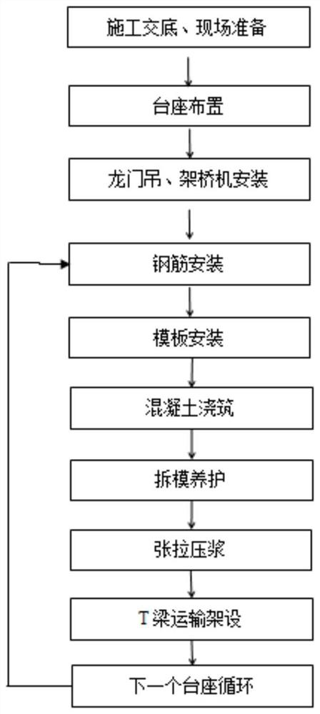
[0047] like Figure 1-4 As shown, the construction method of prefabrication and installation of T beams in the bridge tunnel includes the following steps:

[0048] Step 1: Prepare the construction site and arrange the assembly line system; according to the construction technology and the process sequence, rationally design the production line layout; each production line is set up with a pedestal layout area, a steel bar production area, a beam making area, a maintenance area, and a preliminary tension area. Maintenance area, secondary tension area, beam storage area; gantry cranes and bridge erection machines are commissioned to manufactur...


PUM

PropertyMeasurementUnit
strengthaaaaaaaaaa

Abstract

The invention discloses a construction method for prefabricating and installing a T-beam in a bridging tunnel. The construction method comprises the steps that firstly, a construction site is prepared, and an assembly line system is arranged; reasonably designing a production line layout diagram according to a construction technology disclosure process sequence; each production line is provided with a pedestal arrangement area, a steel bar manufacturing area, a beam manufacturing area, a maintenance area, a primary tensioning area, a maintenance area, a secondary tensioning area and a beam storage area. A gantry crane and a bridge girder erection machine are entrusted to be manufactured by professional manufacturers, and the sizes of the gantry crane and the bridge girder erection machine are limited due to limitation of the height and the width of a tunnel. According to the method, the T-beam is prefabricated in the tunnel, the situation that the T-beam is prefabricated from a farther beam yard and transported to the site for installation is avoided, the construction period is shortened, the transportation cost is reduced, meanwhile, the safety risk is reduced, the beam plates are prefabricated in the tunnel, and due to the fact that sunlight in the tunnel is little and the water loss speed is low, T-beam maintenance is easier compared with outdoor conditions; the time for the concrete to reach the design strength is greatly shortened, and the T-beam tension grouting time is averagely shortened by 1-2 days.

Description

technical field [0001] The invention relates to the technical field of T-beam prefabrication, in particular to a T-beam prefabrication and installation construction method in a bridge tunnel. Background technique [0002] In the construction of highways in mountainous areas, the proportion of bridges and tunnels is getting higher and higher. Some bridges and tunnels have short-circuit foundations, and some bridges and tunnels have no road foundations, which brings great difficulties to bridge construction. The superstructure of bridges The beam and slab can only be transported from the beam yard at other locations to the site for installation after the tunnel is penetrated. The transportation distance is long and the construction period and transportation safety are difficult to guarantee. [0003] In order to solve the problem of limited space between bridges and tunnels in the construction of highways in mountainous areas, and the problem that beams and slabs cannot be pre...

Claims


Application Information

Patent Timeline
Patent Type & Authority Applications(China)
IPC IPC(8): B28B15/00B28B23/04B28B1/04B28B11/24
CPCB28B15/00B28B23/04B28B1/045B28B11/245Y02E10/20
Inventor 伍伦高石茂发马利波李兆宇杨康孙道光尹彪李启怀龙家友
Owner THE FOURTH CONSTR OF YUNNAN ARCHITECTURAL ENG GROUP
Why Eureka
Try Eureka