Steel frame float type offshore photovoltaic platform

A floating platform and buoy-type technology, applied in the field of photovoltaic power generation, can solve problems such as being unsuitable for marine environment and unable to meet the intensity of offshore wind and waves, and achieve the effects of increasing additional hydrodynamic quality, improving motion performance and high reliability

Pending Publication Date: 2022-08-05
HUANENG CLEAN ENERGY RES INST
View PDF8 Cites 6 Cited by
  • Summary
  • Abstract
  • Description
  • Claims
  • Application Information

AI Technical Summary

Problems solved by technology

Considering the harsher marine environment, the high-density polyethylene floating body scheme used in inland waters cannot meet the strength of sea w

Method used


Image

  • Steel frame float type offshore photovoltaic platform
  • Steel frame float type offshore photovoltaic platform
  • Steel frame float type offshore photovoltaic platform

Examples


Embodiment 1

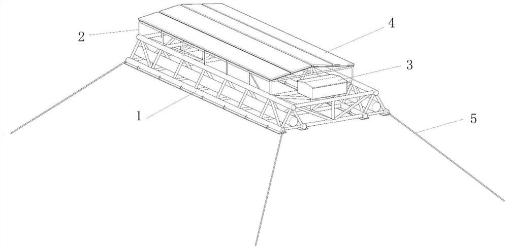
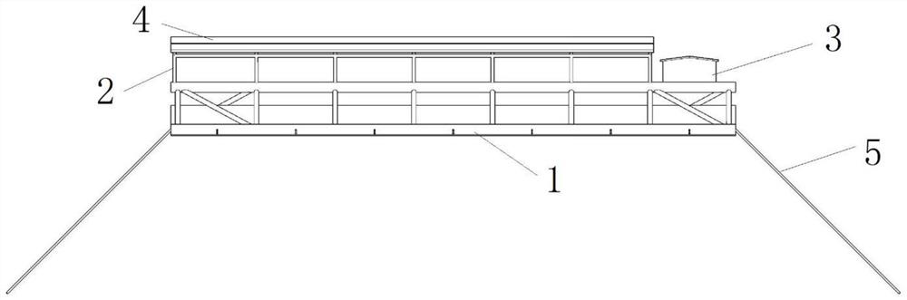
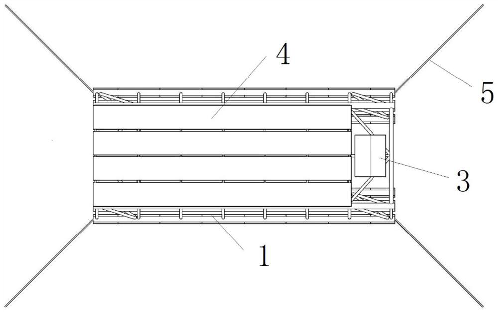
[0032] refer to Figure 1 to Figure 4 , a steel-frame pontoon-type offshore photovoltaic platform, comprising a steel-frame floating platform 1 , a photovoltaic support 2 , a photovoltaic panel 4 , a photovoltaic inverter 3 and several anchor chains 5 . The power generated by the photovoltaic panels 4 is converted into alternating current by the photovoltaic inverter 3 to convert the direct current generated by the photovoltaic modules into alternating current, and then sent to the onshore substation through the submarine cable after confluence.

[0033] The photovoltaic support 2 is fixed directly above the steel-frame floating platform 1 by welding, the photovoltaic inverter 3 is installed on the top of the steel-frame floating platform 1, the photovoltaic panel 4 is installed on the top of the photovoltaic support 2, and the steel-frame floating platform 1 and 4 The corners are respectively connected with one end of the four anchor chains 5, and the other ends of the anchor...

Embodiment 2

[0046] The steel-frame pontoon-type offshore platform can also be expanded by arranging three or more triangular lattice-type steel frames, and installing the corresponding square-type lattice-type steel frames to form a larger-sized steel-frame pontoon-type offshore photovoltaic platform.

[0047] refer to Figure 7 , a steel-frame pontoon-type offshore photovoltaic platform, comprising two steel-frame floating platforms 1 , two photovoltaic supports 2 , photovoltaic panels 4 , two photovoltaic inverters 3 and four anchor chains 5 .

[0048] Two steel-frame floating platforms 1 are arranged side by side and are welded together. The triangular lattice steel frame 110 in the middle of the two steel-frame floating platforms 1 is shared, and two photovoltaics are welded on the two steel-frame floating platforms 1 respectively. Support 2, one of the square lattice steel frames 120 on both sides is reserved as an operation and maintenance channel, and a photovoltaic inverter 3 is i...


PUM

PropertyMeasurementUnit
Heightaaaaaaaaaa

Abstract

The invention discloses a steel frame float type offshore photovoltaic platform, which comprises a steel frame floating platform, a photovoltaic support, a photovoltaic panel, a photovoltaic inverter and an anchor chain, and is characterized in that the photovoltaic support and the photovoltaic inverter are installed on the steel frame floating platform, and the photovoltaic panel is installed at the top of the photovoltaic support; the photovoltaic panel is electrically connected with the photovoltaic inverter; the steel frame is provided with a buoy in a floating mode, a plurality of anchor chains are installed at the lower end of the steel frame floating platform, and the anchor chains are used for mooring the steel frame floating platform on a seabed. The overall structural strength is higher, and reliability is high. The buoy is used for providing main buoyancy for the whole platform, so that small-diameter steel pipes can be adopted, and the manufacturing cost of the floating body is reduced. The platform is low in manufacturing cost, high in strength and suitable for low-cost large-scale development of floating type photovoltaics in deep and far sea.

Description

technical field [0001] The invention belongs to the technical field of photovoltaic power generation, and particularly relates to a steel-frame buoy-type offshore photovoltaic platform. Background technique [0002] In recent years, freshwater photovoltaics have achieved rapid development, and a large number of floating photovoltaic projects have been built in freshwater reservoirs and lakes in China. However, projects such as photovoltaic power stations and wind power generation in the future shall not be constructed in rivers, lakes and reservoirs. Construction of photovoltaic and wind power projects around lakes, reservoirs and reservoirs must be scientifically demonstrated and strictly controlled. This means that it will be more difficult to build floating photovoltaic projects in inland waters in the future. The development of floating photovoltaics needs to explore new ways. China has a sea area of ​​3 million square kilometers, and the huge sea area means that ther...

Claims


Application Information

Patent Timeline
IPC IPC(8): B63B35/44H02S20/30
CPCB63B35/44H02S20/30B63B2035/4453Y02E10/727Y02E10/50
Inventor 刘鑫雷宇陈建军周昳鸣刘瑞超
Owner HUANENG CLEAN ENERGY RES INST
Why Eureka
Try Eureka