
Cross interconnection high-voltage cable sheath current off-line detection time synchronization method and system

A sheath current, high-voltage cable technology, applied in the direction of measuring current/voltage, information technology support system, measuring device, etc., can solve the problem of limiting the application of sheath current detection technology, unable to apply offline mobile inspection, unable to realize current signal time Synchronization, etc.

Pending Publication Date: 2022-08-05
STATE GRID CORP OF CHINA +1
View PDF0 Cites 0 Cited by
  • Summary
  • Abstract
  • Description
  • Claims
  • Application Information

AI Technical Summary

Problems solved by technology

In the past, the distributed on-line monitoring of the sheath ground current of the cross-connected high-voltage cable system relied on GPS or local network hardware time synchronization. Due to the limitation of no signal in the underground cable channel and the limitation of networking costs, it could not be applied to offline mobile inspection, which limited the sheath current. Application of Detection Technology in Offline Scenarios
When there is no GPS signal and local network, it is impossible to realize the time synchronization of the distributed sheath current signal of high-voltage cables

Method used


Image

  • Cross interconnection high-voltage cable sheath current off-line detection time synchronization method and system
  • Cross interconnection high-voltage cable sheath current off-line detection time synchronization method and system
  • Cross interconnection high-voltage cable sheath current off-line detection time synchronization method and system

Examples


Embodiment Construction

[0095] The following combined with the attached figures, the principle and characteristics of the present invention are described. The examples are used to explain the present invention, not to limit the scope of the present invention.

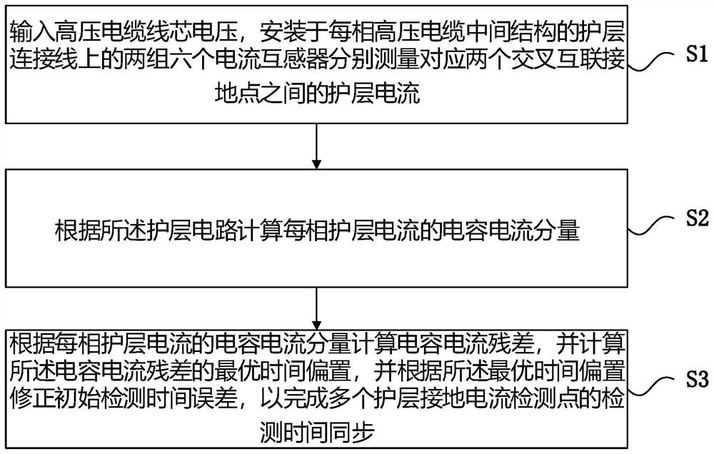
[0096] like figure 1 Show, a cross -line detection time synchronization method of cross -interconnection high -voltage cable protection layer, including the following steps:

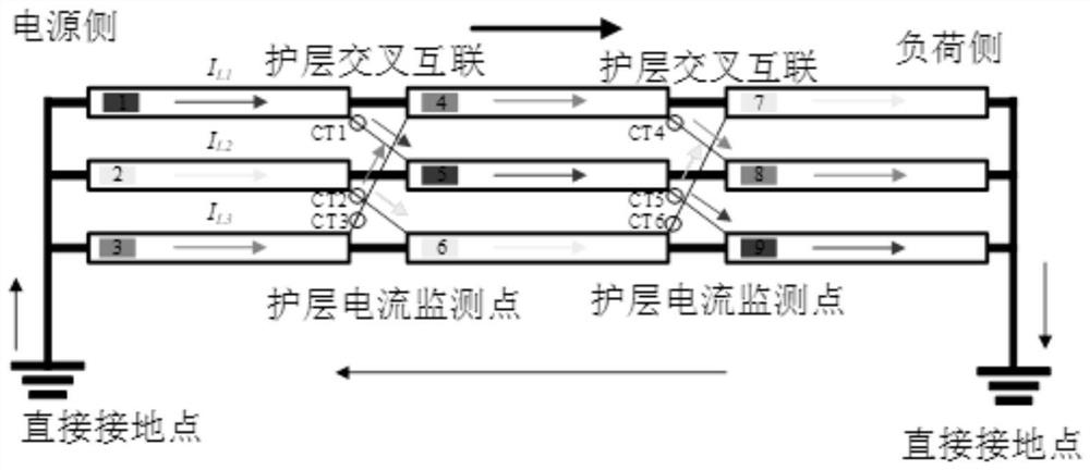
[0097] S1: Enter the voltage of the high -voltage cable core, and the two sets of six current transformers installed on the intermediate structure of each high -pressure cable are measured by the two sets of current transformers on the connection line of the connection line.

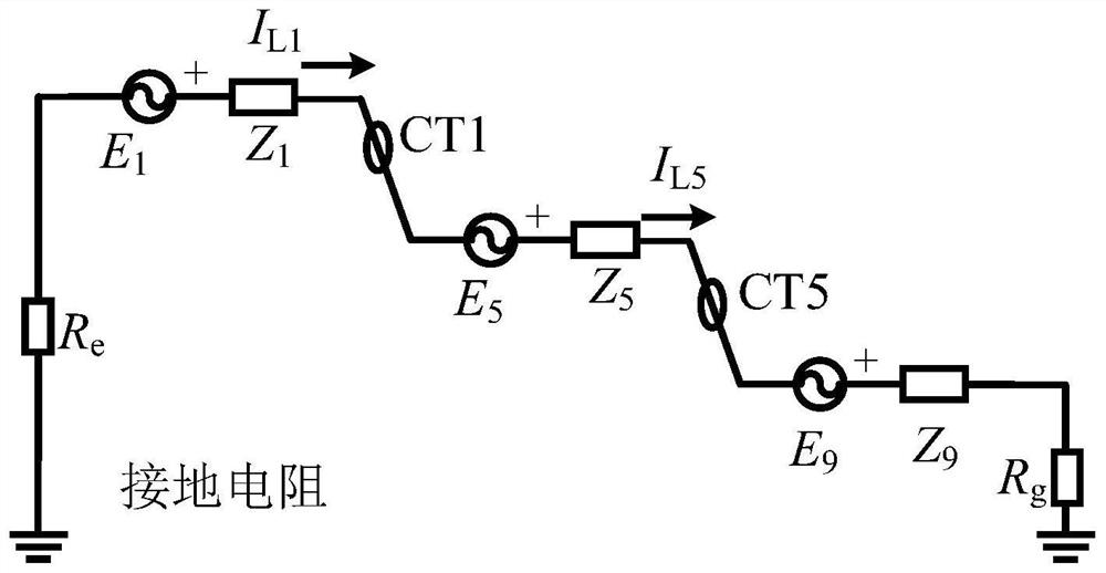
[0098] S2: Calculate the capacitance current component of each phase of the carrier layer according to the care layer circuit;

[0099] S3: Calculate the capacitor current residual according to the capacitance current component of each care layer, and calculate the optimal time bias of the capacitance ...


PUM


Abstract

The invention relates to a cross-interconnected high-voltage cable sheath current off-line detection time synchronization method and system, and the method comprises the steps: inputting the voltage of a high-voltage cable core, and respectively measuring the sheath current between two corresponding cross-interconnected grounding points; calculating a capacitance current component of each phase of sheath current according to the sheath circuit; and calculating a capacitance current residual error according to the capacitance current component of each phase of sheath current, calculating the optimal time offset of the capacitance current residual error, and correcting the initial detection time error according to the optimal time offset so as to complete the time synchronization of the plurality of sheath grounding current detection points. According to the method, the capacitive current component and the capacitive current residual error in each phase of sheath current are calculated through the sheath current to determine the optimal time bias, so that the sampling initial time deviation of the power supply side and the load side is corrected, the time synchronization of a plurality of sheath grounding current monitoring points is realized, the sheath current vector can be accurately extracted, and the detection accuracy is improved. And the diagnosis of the grounding fault of the crossed and interconnected high-voltage cable sheath is guided.

Description

Technical field [0001] The present invention involves the field of high -voltage cable detection technology, especially involving cross -line detection time synchronization methods and systems for cross -interconnected high -voltage cable guards. Background technique [0002] Protective layer current is the key state quantity of diagnosis of cross -interconnected high -voltage cable protective layers. The time synchronization of distributed protective layer current measurement signals is the prerequisite for accurate extraction of the protective layer. In the past cross -interconnected high -voltage cable system protective ground current distributed online monitoring relying on GPS or local network hardware pairs, it was not applied to offline mobile inspections without signal and networking costs of underground cable channels. The application of detection technology in offline scenes. When there is no GPS signal and a local network, the problem of the current signal of a distrib...

Claims


Application Information

Patent Timeline
Patent Type & Authority Applications(China)
IPC IPC(8): G01R19/00G01R31/08
CPCG01R19/0092G01R31/083G01R31/088Y04S10/52
Inventor 李新国曾海燕杨斌高新昀涂京严一涛李欣然邓罡
Owner STATE GRID CORP OF CHINA
Learn More