Miniature flat piezoelectric motor and design method

A piezoelectric motor and design method technology, applied in piezoelectric effect/electrostrictive or magnetostrictive motors, generators/motors, electrical components, etc., can solve the problems of difficult miniaturization, limited application, etc. The effect of small, small excitation voltage amplitude and large output performance

Active Publication Date: 2022-08-05
ZHEJIANG LAB
View PDF4 Cites 0 Cited by
  • Summary
  • Abstract
  • Description
  • Claims
  • Application Information

AI Technical Summary

Problems solved by technology

The biggest advantage of the thin-plate motor is its simple structure, flatness, and light weight, which are suitable for the transportation of light and thin objects. However, for this type of motor, the frequency tuning of the longitudinal-bending composite mode limits the in-plane vibration of rectangular plates. The aspect ratio makes it difficult to further miniaturize this type of motor, which limits its application in the field of in vivo medical devices

Method used


Image

  • Miniature flat piezoelectric motor and design method
  • Miniature flat piezoelectric motor and design method
  • Miniature flat piezoelectric motor and design method

Examples


Embodiment 1

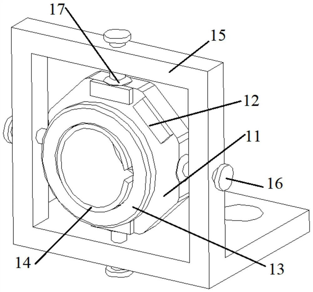
[0041] The piezoelectric ceramic sheet 12 is pasted on the outer surface of the metal base 11 to form a stator; the rotor 14 is an annular structure with a certain opening, and the rotor 14 is embedded in the hollow metal base 11 through threads, and is driven by the threads. The piece 13 moves helically along the axis of the metal base 11 . The support frame 15 is an L-shaped structure, wherein the vertical part of the support frame 15 is a hollow structure for fixing the metal base 11 , and a first through hole is opened in the vertical part of the support frame 15 to apply pressure to the metal base 11 . pre-pressure. In this embodiment, four first through holes are symmetrically formed in the vertical part of the support frame 15 , the fastening nuts 16 are inserted into the first through holes of the vertical part of the support frame 15 , and the pressure is evenly applied to the metal base 11 through the disc spring 17 . In this way, the applied pre-pressure can only act...

Embodiment 2

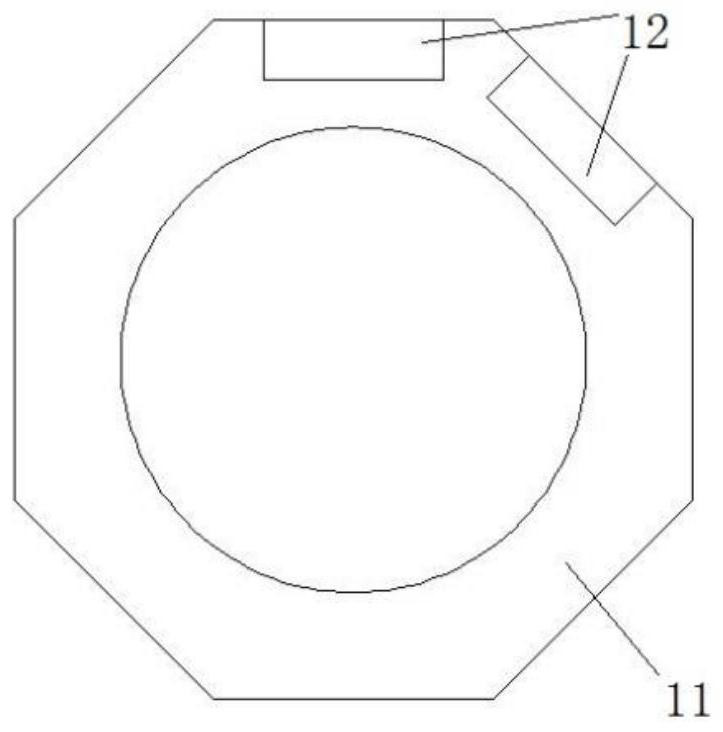
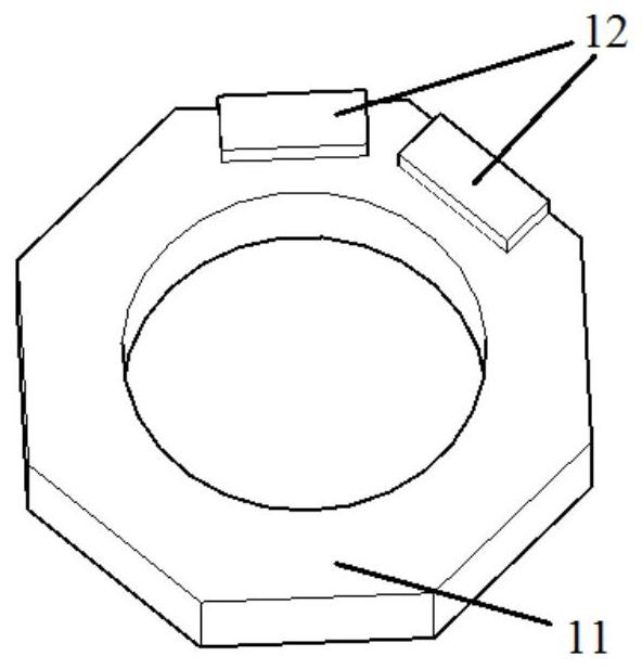
[0045] In order to further increase the output displacement of the motor, the present invention proposes an improved stator structure, whose top view is as follows: Figure 4 shown. It includes a metal base 11 and two sets of piezoelectric ceramic sheets 12 . The metal base 11 is brass, and the two groups of piezoelectric ceramic sheets 12 are symmetrically pasted by epoxy resin glue, and each group contains two pieces, the piezoelectric ceramic sheets in each group are pasted adjacently, and each piezoelectric ceramic sheet is attached thickness direction polarization. When two sets of piezoelectric ceramic sheets 12 in the stator are respectively excited by two-phase sinusoidal AC voltages with a peak value of 50V and a phase difference of 90°, the maximum vibration displacement in the x and y directions at the driving point of the stator 12 is measured to be is to adopt figure 2 The stator structure shown in , and two times of the maximum output displacement generated w...

Embodiment 3

[0048] The present invention also proposes such as Figure 5 shown stator structure, which is the same as figure 2 The difference in the stator construction shown in is the rounded corners on the metal base. It is obtained through simulation analysis, and figure 2 Compared to the performance of the stator shown in, Figure 5 The output displacement of the stator drive surface particles shown in is larger, and the specific displacement magnification is the same as Figure 5 It is related to the radius of the fillet opened in . In addition, it is also possible to Figure 5 Two sets of piezoelectric ceramic sheets are pasted on the stator structure shown in Figure 4 The stator structure diagram. Similarly, after rounding the corners, the output displacement of the stator driving surface particles is also higher than that of using Figure 4 The structure shown is larger, and the specific displacement magnification is determined by the rounded corners.

[0049] Other par...


PUM


Abstract

The invention discloses a miniature flat piezoelectric motor and a design method, and relates to the field of piezoelectric motors, the miniature flat piezoelectric motor comprises a stator, the stator comprises a metal matrix and a plurality of piezoelectric ceramic pieces, and the piezoelectric ceramic pieces are symmetrically arranged on the metal matrix; the rotor is arranged in the metal base body; the driving part is arranged between the inner wall of the stator and the rotor, and the rotor drives the driving part to spirally move along the axis of the metal matrix; the supporting frame is used for fixing the metal base body and exerting pressure on the metal base body. According to the miniature flat piezoelectric motor and the method, the size of the motor is smaller, the output performance of the motor is higher, the adjustable range of the performance is wider, and the miniature flat piezoelectric motor is particularly suitable for the field of medical instruments such as endoscopes, endoscopic capsules and micro-injection pumps which need to be precisely controlled by a miniature driver.

Description

technical field [0001] The present application relates to the field of piezoelectric motors, and in particular, to a micro-plate piezoelectric motor and a design method. Background technique [0002] Different from the traditional electromagnetic motor, the piezoelectric motor is a new principle motor, which uses the inverse piezoelectric effect of piezoelectric ceramics to make the stator vibrate slightly, and then vibrates the stator slightly through the friction of the contact interface between the stator and the rotor. Converted to the macroscopic motion of the mover. Therefore, piezoelectric motors have the characteristics of compact structure, no electromagnetic interference, easy miniaturization, and high energy density, which make piezoelectric motors successfully used in many fields such as digital cameras, biomedical therapy, aerospace equipment, and precision systems. [0003] Piezoelectric motors based on in-plane vibration have received extensive attention due ...

Claims


Application Information

Patent Timeline
Patent Type & Authority Applications(China)
IPC IPC(8): H02N2/12H02N2/14
CPCH02N2/12H02N2/14
Inventor 李冲高大陈睿黾施钧辉
Owner ZHEJIANG LAB
Why Eureka
Try Eureka