Balloon dilatation catheter

A technique for dilating catheters and balloons, which can be used in balloon catheters, dilators, surgery, etc., to solve problems such as inability to locate lesions, uneven balloon expansion, stent displacement, etc., to increase operation time and Risk, reduce treatment costs and physical burden, deliver accurate effects

Pending Publication Date: 2022-08-09
JIANGSU PNP MEDTECH CO LTD
View PDF0 Cites 0 Cited by
  • Summary
  • Abstract
  • Description
  • Claims
  • Application Information

AI Technical Summary

Problems solved by technology

When the traditional balloon dilatation catheter is inflated with the implant, the liquid enters the interior from one end of the balloon, causing the partial expansion of the balloon first, resulting in uneven expansion of the balloon
When treating large lesions, it is necessary to use a balloon with a large diameter. Such an uneven expansion method will make the filling and decompression time of the large balloon too long, the stent will shift, and the location of the lesion cannot be well positioned.

Method used


Image

  • Balloon dilatation catheter
  • Balloon dilatation catheter
  • Balloon dilatation catheter

Examples


no. 1 example

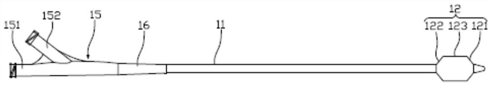
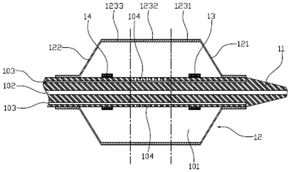
[0032] figure 1 is a schematic structural diagram of the balloon dilatation catheter according to the first embodiment of the present application, figure 2 It is a partial cross-sectional structural schematic diagram of the balloon dilation catheter according to the first embodiment of the present application, such as figure 1 and figure 2 As shown, the balloon dilatation catheter includes a multi-lumen tube 11 and a balloon 12. The multi-lumen tube 11 is provided with a guide wire lumen 102 and at least one fluid passage channel 103. The balloon 12 is connected to the fluid outlet of the multi-lumen tube 11. A liquid-filled cavity 101 is formed between the balloon 12 and the multi-lumen tube 11. The section of the multi-lumen tube 11 located in the liquid-filled cavity 101 is provided with a plurality of liquid outlet areas, and the plurality of liquid outlet areas are located along the multi-lumen tube 11. Each liquid outlet area is provided with at least one liquid outl...

no. 2 example

[0054] image 3 It is a partial cross-sectional structural schematic diagram of the balloon dilation catheter of the second embodiment of the present application, such as image 3 As shown, the structure of the balloon dilatation catheter of the present embodiment is substantially the same as that of the balloon dilation catheter of the first embodiment, and the difference lies in the arrangement position of the liquid outlet hole 104 .

[0055] Optionally, as image 3 As shown, the multiple liquid outlet areas on the multi-lumen tube 11 are located in the area covered by the first connecting section 121 , the middle straight section 123 and the second connecting section 122 , that is to say, the multi-lumen tube 11 is located in the liquid-filled cavity 101 . Each section is provided with a liquid outlet area, which is more than that provided only in the area covered by the second straight portion 1232, and the number of the liquid outlet holes 104 increases, increasing the ...

no. 3 example

[0058] Figure 4 It is a partial cross-sectional structural schematic diagram of the balloon dilation catheter according to the third embodiment of the present application, as shown in Figure 4 As shown, the structure of the balloon dilation catheter of this embodiment is substantially the same as that of the first embodiment or the second embodiment, the difference is that the multi-lumen tube 11 of this embodiment is located in the tube wall of the liquid-filled cavity 101 There is a coating 17 thereon.

[0059] Optionally, as Figure 4 As shown, the coating 17 covers all or part of the liquid outlet hole 104, and the coating 17 is soluble in water-soluble liquid; the coating 17 can be disposed on the multi-lumen tube 11 by coating, and is cured by ultraviolet light to achieve The liquid outlet hole 104 is blocked; when the coating 17 is in contact with the water-soluble liquid, it can dissolve rapidly, for example, within 0.1-3s. In this embodiment, the coating 17 is so...


PUM


Abstract

The balloon dilatation catheter comprises a multi-cavity tube and a balloon, a guide wire cavity channel and at least one liquid passing cavity channel are formed in the multi-cavity tube, the balloon is connected to the liquid outlet end of the multi-cavity tube, a liquid filling cavity is formed between the balloon and the multi-cavity tube, a plurality of liquid outlet areas are arranged on the section, located in the liquid filling cavity, of the multi-cavity tube, and the liquid outlet areas are arranged in the axial direction of the multi-cavity tube. Each liquid outlet area is provided with at least one liquid outlet hole, and the liquid outlet holes are communicated with the liquid passing cavity channel and the liquid filling cavity. According to the balloon dilatation catheter, the balloon can be uniformly dilated, and the treatment cost is reduced.

Description

technical field [0001] The present application relates to the technical field of medical devices, in particular to a balloon dilatation catheter. Background technique [0002] Percutaneous transluminal angioplasty (PTA) is a minimally invasive vasodilator surgery for the treatment of human vascular stenosis and occlusion. It refers to the use of percutaneous puncture technology to insert a balloon dilatation catheter into the stenosis of the blood vessel, under the guidance and monitoring of medical imaging equipment to pressurize the balloon, through mechanical expansion, the deformation of intravascular atheromatous plaque or thrombus or the expansion of the blood vessel itself, etc. , thereby changing the diameter of blood vessels and achieving revascularization. PTA is a major advance in the treatment of vascular disease. The main mechanism of balloon vasodilation is that the balloon dilation separates the stenotic and sclerotic intima, and at the same time destroys th...

Claims


Application Information

Patent Timeline
Patent Type & Authority Applications(China)
IPC IPC(8): A61M25/10A61M29/02
CPCA61M25/10181A61M25/104A61M29/00A61M2025/1079A61M2025/105
Inventor 盛泽元顾凡周毅
Owner JIANGSU PNP MEDTECH CO LTD
Why Eureka
Try Eureka