Machining method of crank pin and crank pin

A processing method and crank pin technology, applied in bolts and other directions, can solve problems such as material loss, and achieve the effect of reducing raw material loss and solving serious material loss

Active Publication Date: 2022-08-09
GUIZHOU AEROSPACE PRECISION PRODS
View PDF5 Cites 0 Cited by
  • Summary
  • Abstract
  • Description
  • Claims
  • Application Information

AI Technical Summary

Problems solved by technology

[0003] Previously, the processing of crank pins was: using φ69 bar stock for rough machining of the head, the outer circle of the rod and the rod, followed by wire cutting, digital milling of the head and drilling. Although, this processing method can realize the one-piece crank pin structure processing, however, there is a serious material loss problem in this processing method

Method used


Image

  • Machining method of crank pin and crank pin
  • Machining method of crank pin and crank pin
  • Machining method of crank pin and crank pin

Examples


Embodiment Construction

[0028] The technical solutions of the present invention are further described below, but the claimed scope is not limited to the description.

[0029] like Figure 1 to Figure 7 shown.

[0030] A processing method of a crank pin of the present invention comprises the following steps:

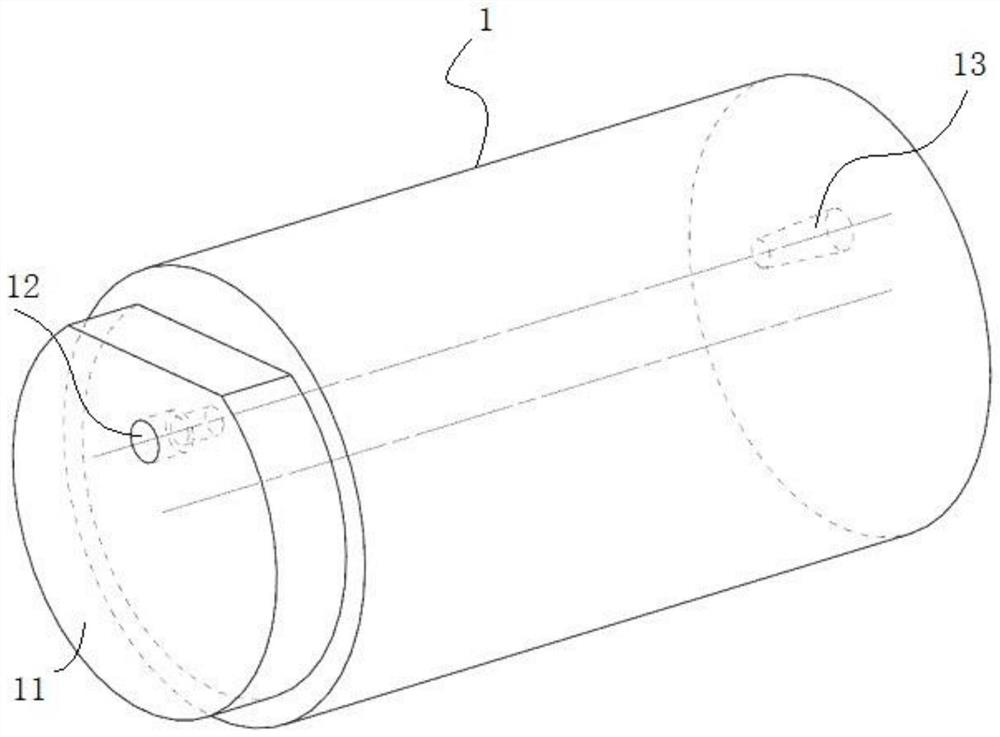
[0031] Step 1. Bar hoof forming: Take φ57 round bar 1, use a CNC milling machine to mill out the hoof table 11 at one end of the bar 1, and reserve the allowance for the maximum distance dimension of the head 51 of the crank pin 5 Processing, because the shoe-shaped table 11 needs to be processed to form the head 51 of the crank pin 5 in the later stage.

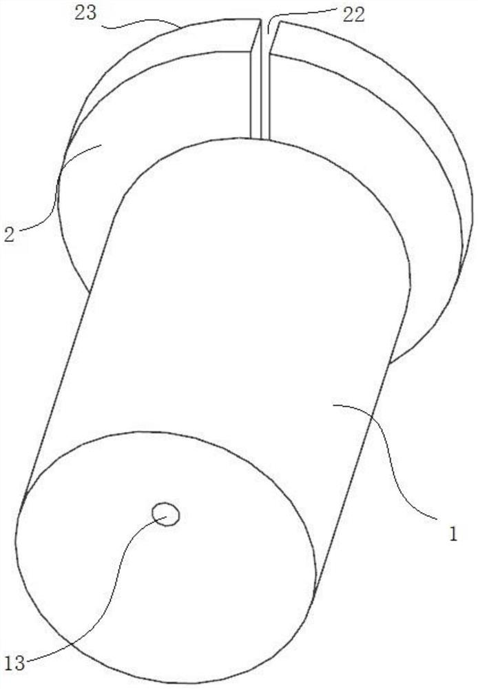
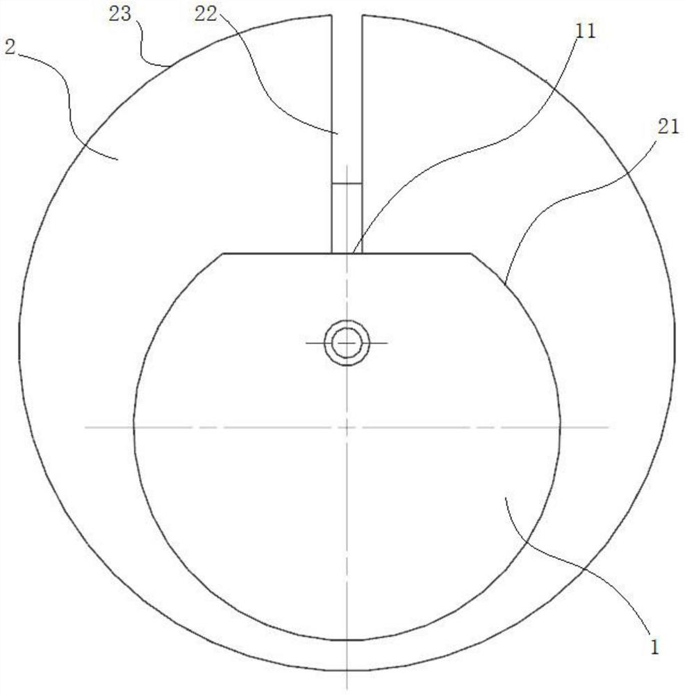
[0032] Step 2. Forming of the center hole: the hoof-shaped hole 21 of the hoof-shaped tooling body 2 is used to cooperate with the hoof-shaped table 11 of the bar 1, and the lathe clamp is clamped by clamping the outside of the hoof-shaped tooling body 2, and the hoof-shaped tooling body 2 is in the Under the deformation of the hoof-shaped ...


PUM


Abstract

The machining method comprises the step of forming a center hole, specifically, a horseshoe-shaped hole of a horseshoe-shaped tool body is matched with a horseshoe-shaped table of a bar, and the center hole A and the center hole B which are concentric are machined in the two ends of the bar with the center axis of the large-diameter outer circle of the horseshoe-shaped tool body as the axis. After the horseshoe-shaped hole of the horseshoe-shaped tool body is matched with the horseshoe-shaped table of the bar, the center of the large-diameter outer circle of the horseshoe-shaped tool body coincides with and is concentric with the circle center of the rod part through hole of the crank pin to be machined later, and a center hole A and a center hole B which are concentric are machined in the two ends of the bar. And lathing the rod part of the crank pin on a lathe by taking the center of the central hole A and the center of the central hole B as the axis in the later stage, and machining and forming the head part and the head part eccentric hole by taking the axis of the rod part as the reference. And the problem of serious material loss of the processing mode is solved.

Description

technical field [0001] The invention relates to a processing method of a crank pin and a crank pin, belonging to the technical field of crank pins. Background technique [0002] In order to realize the conversion of rotary motion and linear motion, a crank-rocker mechanism is used, such as a road greening and trimming mechanism for municipal engineering with the Chinese Patent Publication No. CN213073667U. The disclosed technology is: the output end of the power drive box is fixedly installed with a Crank disc, crank pin is fixedly installed on the surface of the crank disc, and the surface of the crank pin is movably sleeved with a reciprocating shearing mechanism; the reciprocating collar is movably sleeved on the outside of the crank pin to realize the drive of the reciprocating shearing mechanism; although, The crank disc and the crank pin can be fixed in the reciprocating collar, but sometimes, in order to meet the strength requirements, the crank disc and the crank pin...

Claims


Application Information

Patent Timeline
Patent Type & Authority Applications(China)
IPC IPC(8): B23P15/00F16B19/02
CPCB23P15/00F16B19/02Y02P70/10
Inventor 陈实冉杰董贵芳李鸿王科祁中强唐林吴英宏牟军汪健韦华
Owner GUIZHOU AEROSPACE PRECISION PRODS
Why Eureka
Try Eureka