
End grinding machine of linear probe

A technology of end grinder and end grinder, which is applied in the direction of machine tools, grinders, and grinding drive devices suitable for grinding the edge of workpieces. Effects of excessive grinding, deburring and improvement of pass rate

Active Publication Date: 2022-08-09
SUZHOU UIGREEN MICRO & NANO TECH CO LTD
View PDF11 Cites 0 Cited by
  • Summary
  • Abstract
  • Description
  • Claims
  • Application Information

AI Technical Summary

Problems solved by technology

[0004] At present, the method of rotating and straightening is usually used to straighten the coiled wire, but after this straightening method, burrs will be generated on the cut surface, and the cut will be deformed, which causes great defects for subsequent processing.
Moreover, the diameter of this kind of probe generally does not exceed 0.05mm, which is thinner than a hair, so it is very difficult to clamp and process.
Therefore, the incision part must be polished before subsequent processing, otherwise the defective rate is too high, resulting in very high manufacturing costs

Method used


Image

  • End grinding machine of linear probe
  • End grinding machine of linear probe
  • End grinding machine of linear probe

Examples


Embodiment Construction

[0062] The technical solutions in the embodiments of the present invention will be clearly and completely described below with reference to the accompanying drawings in the embodiments of the present invention.

[0063] In the description of the present invention, it should be understood that the terms "upper", "lower", "front", "rear", "left", "right", "top", "bottom", "inside", " The orientation or positional relationship indicated by "outside" is based on the orientation or positional relationship shown in the accompanying drawings, and is only for the convenience of describing the present invention and simplifying the description, rather than indicating or implying that the indicated device or element must have a specific orientation, so as to The specific orientation configuration and operation are therefore not to be construed as limitations of the present invention.

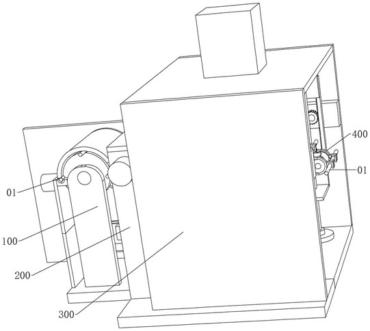
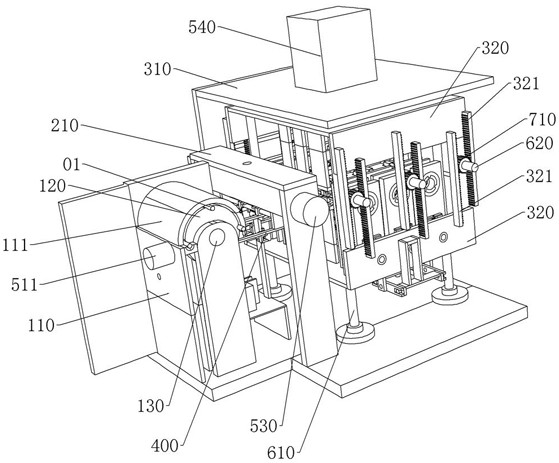
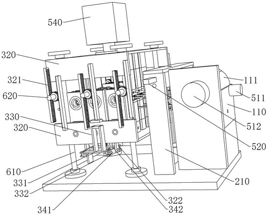
[0064] see Figure 1-Figure 9 , a linear probe end mill of this embodiment includes a transfer module ...


PUM


Abstract

The invention discloses an end grinding machine for a linear probe. The end grinding machine can grind the two ends of a probe section. Comprising an end grinding module, the end grinding module comprises an end grinding frame, two clamping frames distributed up and down are installed in the end grinding frame, and a needle section needing to be machined is located between the two clamping frames; different end grinding mechanisms are further installed at the positions, located at the two ends of the needle section, of one clamping frame, and the end grinding mechanisms are used for grinding the ends of the needle section. The end grinding mechanism comprises a first end grinding plate, a second end grinding plate and a third end grinding plate, the first end grinding plate is assembled with an end grinding pipe, one end of the end grinding pipe penetrates out of the third end grinding plate after penetrating through a pipe sleeve, the pipe sleeve is assembled with the second end grinding plate and the third end grinding plate, and the end grinding pipe is assembled with the pipe sleeve; an end grinding plug is mounted on the end grinding pipe and is used for grinding the end part of the needle section; the second end grinding plate and the third end grinding plate are respectively assembled with an end grinding screw sleeve, and the end grinding screw sleeve is sleeved on a third end grinding shaft; the first end grinding plate and the end grinding screw sleeve are directly or indirectly assembled in a screwed mode through threads.

Description

technical field [0001] The invention relates to the technical field of production of linear probes, in particular to an end mill for linear probes. Background technique [0002] Linear probes are mainly used in genetic testing, and their diameter is generally not more than 0.05mm. When used, the needle tip of the linear probe pierces the oxide layer of the chip to meet the electrical performance test requirements of the chip. Because the linear probe is very thin, it is very difficult to set up, and the processing accuracy is also very high. [0003] At present, foreign countries mainly use metal rods to draw wires with small diameters, and then roll them up. The stress generated in the production process of the wire will cause the coiled wire to bend during the unwinding process, and the straightness cannot meet the requirements of the needle. Therefore, it is necessary to straighten the coiled wire again and cut it into a needle of a certain length, and then grind one end...

Claims


Application Information

Patent Timeline
Patent Type & Authority Applications(China)
IPC IPC(8): B24B9/04B24B27/00B24B41/06B24B41/00B24B49/00B24B47/20
CPCB24B9/04B24B27/0076B24B41/06B24B41/005B24B27/0023B24B27/0069B24B49/00B24B47/20
Inventor 钱晓晨郭爱民缪拥正
Owner SUZHOU UIGREEN MICRO & NANO TECH CO LTD
Learn More