
Rock slope protection structure and construction method

A technology for slope protection and rock mass, which is applied in basic structure engineering, botanical equipment and methods, excavation, etc., can solve the problems of inconvenient maintenance, high maintenance cost, and high cost input, achieve simple protection, improve greening effect, And the effect of alleviating the pressure and impact of water flow

Pending Publication Date: 2022-08-09
GEOLOGICAL INVESTIGATION & FOUNDATION CONSTR CO OF HUBEI PROVINCE
View PDF6 Cites 0 Cited by
  • Summary
  • Abstract
  • Description
  • Claims
  • Application Information

AI Technical Summary

Problems solved by technology

[0004] The purpose of the present invention is to aim at the existing slope protection existing in the background technology in the form of cement mortar pouring, which is used to improve the adhesion of gravel, but the cost of this protection form is high, and it is not convenient for maintenance and repair in the later stage. To solve the problems of high difficulty and high maintenance cost, a rock mass slope protection structure and construction method are proposed

Method used


Image

  • Rock slope protection structure and construction method
  • Rock slope protection structure and construction method
  • Rock slope protection structure and construction method

Examples


Embodiment 1

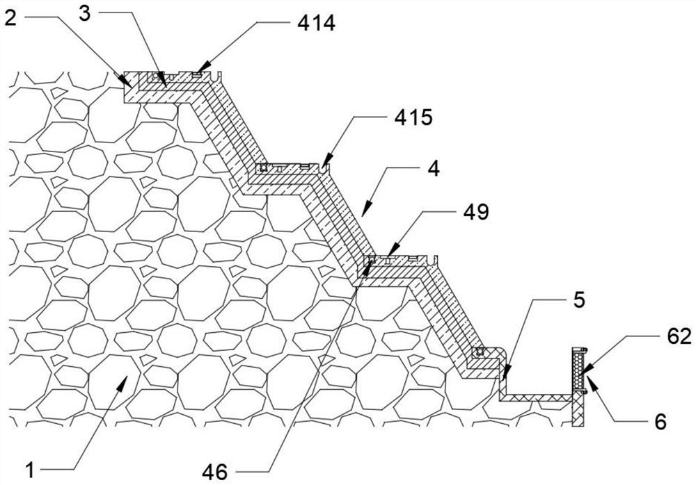
[0035] like Figure 1-5 As shown, a rock mass slope protection structure proposed by the present invention includes a rock layer body 1, the outer layer of the rock layer body 1 is provided with a soil layer 2, and the outer layer of the soil layer 2 away from the rock layer body 1 is provided with a nutrient layer 3 on the outer layer. , one side of the nutrient layer 3 is provided with a protective component 4, and the protective component 4 is a metal steel component;

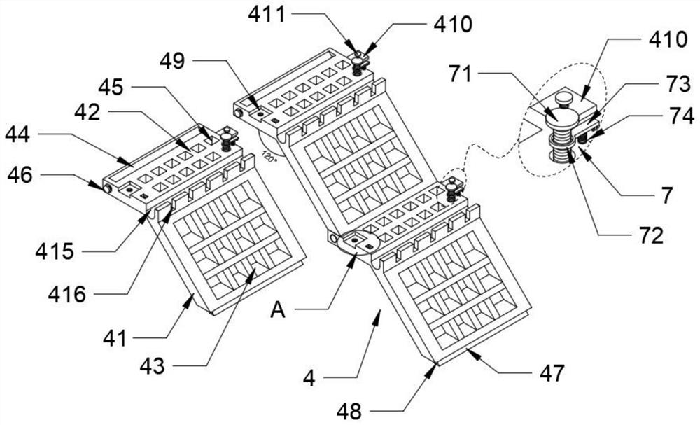
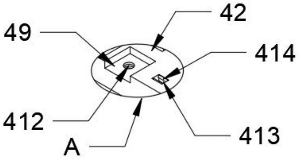
[0036]The protective assembly 4 includes a protective plate one 41 and a protective plate two 42. The protective plate one 41 is inclined by 120° relative to the bottom surface of the protective plate two 42. The first planting hole 43, the protection plate one 41 is also provided with a mounting slot 44, the two sides of the installation slot 44 are rotated and installed with the three bolts 46 located on the second protection plate 42, and the three bolts 46 penetrate the two sides of the mounting slot 44....

Embodiment 2

[0041] like Figure 1-5 As shown in the figure, a construction method of a rock mass slope protection structure proposed by the present invention, compared with the first embodiment, this embodiment also includes a rock formation body 1, and the outer layer of the rock formation body 1 is provided with a soil layer 2, and the soil layer 2 A nutrient layer 3 is arranged on the outer layer of one side away from the rock formation body 1, and a protective component 4 is arranged on one side of the nutrient layer 3;

[0042] The protective assembly 4 includes a protective plate 41 and a protective plate 2 42. The protective plate 2 42 is also provided with a guide channel 415. One side of the guide channel 415 is provided with a plurality of shunt channels 416. The water flowing in 415 is dispersed and transported, reducing the impact force of the water and providing water for the plants planted in the planting hole one 43. The protective plate one 41 is provided with a planting h...

Embodiment 3

[0047] like Figure 1-5 As shown, the construction method of a rock mass slope protection structure proposed by the present invention, compared with Embodiment 1 or Embodiment 2, the construction method includes the following steps:

[0048] Step 1: Arrangement of the rock slope: Lay the soil layer 2 and the nutrient layer 3 on the slope of the rock formation body 1, and arrange the slope of the soil layer 2 and the nutrient layer 3, so that the side of the nutrient layer 3 conforms to the protection component 4. installation requirements;

[0049] Step 2: Lay the protective components 4: Calculate the required number of protective components 4 according to the slope of the rock formation body 1, and assemble the protective components 4 in the same row correspondingly. The assembly of the same row specifically includes the following steps: a. A protective plate above The mounting plate 47 at the bottom of the first 41 is correspondingly buckled with the mounting groove 44 on ...


PUM


Abstract

The invention relates to the technical field of slope protection structures, in particular to a rock mass slope protection structure and a construction method. According to the technical scheme, the slope protection structure mainly aims at solving the problems that existing slope protection mostly adopts a cement mortar pouring mode for improving adhesiveness of gravel, but the protection mode is high in cost input, inconvenient to maintain and trim in the later period, large in construction difficulty and high in maintenance cost, and comprises a rock stratum body, and a soil layer is arranged on the outer layer of the rock stratum body; a nutrient layer is arranged on the outer layer of the side, away from the rock stratum body, of the soil layer, and a protection assembly is arranged on one side of the nutrient layer. The protection structure is novel and compact in structure, convenient to use, low in protection cost and maintenance and finishing cost, convenient for later maintenance and replacement of independent protection assemblies, more convenient and flexible to use, small in construction difficulty, low in later treatment difficulty and good in protection effect, the utilization rate of the protection structure is effectively improved through steel, and the protection structure is mainly applied to protection of rock slopes.

Description

technical field [0001] The invention relates to the technical field of side slope protection structures, in particular to a rock mass side slope protection structure and a construction method. Background technique [0002] The rock slope is a slope composed of various rock masses. The slope protection is mainly to avoid the instability and collapse of the slope under some extreme conditions, resulting in the destruction of the slope protection. The common way is Cutting slopes, hanging nets, soil nailing walls, etc.; the existing slope protection treatment uses cement mortar to cover the rock formation to avoid soil erosion and sand and gravel landslides. The use of spraying, anchoring and net support system can strengthen the rock mass of shallow landslide and developed joints and fissures, and improve the strength of the rock mass. Bolt grouting fills and reinforces the rock mass joints and fissures within a certain range of the bolt and applies prestress to the rock mass...

Claims


Application Information

Patent Timeline
IPC IPC(8): E02D17/20E03F3/04A01G9/02A01G27/00
CPCE02D17/20E03F3/046A01G9/023A01G9/028A01G27/00E02D2600/20Y02A10/23
Inventor 徐建熊兴旺饶晖洪渤周力王能永朱婷黄翼
Owner GEOLOGICAL INVESTIGATION & FOUNDATION CONSTR CO OF HUBEI PROVINCE
Learn More