Industrial electric furnace

An electric furnace and industrial technology, applied in the field of industrial electric furnaces, can solve problems such as waste of resources, damage to industrial electric furnaces, environmental pollution, etc., and achieve the effects of ensuring full utilization, improving uniformity, and reducing costs

Pending Publication Date: 2022-08-09
张相相
View PDF0 Cites 0 Cited by
  • Summary
  • Abstract
  • Description
  • Claims
  • Application Information

AI Technical Summary

Problems solved by technology

[0003] In the traditional industrial electric furnace exhaust gas treatment process, the flue gas displacement changes with the incoming air and temperature changes. If the flue gas cannot be discharged in time, it may cause backflow, which will lead to excessive internal pressure of the industrial electric furnace and exhaust pipe. Easy to cause damage to industrial electric furnace
[0004] The flue gas generated by the industrial electric furnace during the heat treatment of metal parts may be directly treated by the existing toxic gas purification equipment. The heat energy and wind energy in the flue gas are directly discharged to the external environment without utilization, which is likely to cause environmental pollution and cause resource pollution. waste of

Method used


Image

  • Industrial electric furnace
  • Industrial electric furnace
  • Industrial electric furnace

Examples


Embodiment Construction

[0027] The embodiments of the present invention are described in detail below with reference to the accompanying drawings, but the present invention can be implemented in many different ways as defined and covered by the claims.

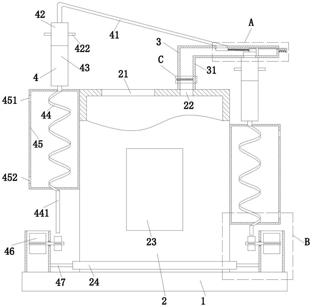
[0028] see figure 1 , an industrial electric furnace, including a base 1, a furnace body 2, an exhaust system 3 and a flue gas reuse system 4, the furnace body 2 is installed in the middle of the upper end face of the base 1, and the upper end face of the furnace body 2 is sequentially from left to right. A feeding port 21 and an air outlet 22 are provided, an exhaust system 3 is installed on the upper end surface of the furnace body 2 and located on the upper side of the air outlet 22, and a flue gas reuse system 4 is installed on the left and right sides of the furnace body 2 and the upper end surface of the base 1. .

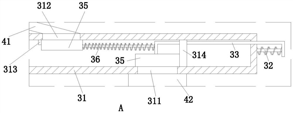
[0029] see figure 1 as well as figure 2 , the exhaust system 3 includes an air outlet pipe 31, a reset spring rod 32, a linkag...


PUM


Abstract

The invention relates to the technical field of industrial heat treatment, in particular to an industrial electric furnace which comprises a base, a furnace body, an exhaust system and a flue gas recycling system.In the exhaust system, when flue gas is exhausted from the interior of the furnace body, flue gas flows to drive a first opening and closing block to move leftwards, and when the first opening and closing block leaves a first opening, the flue gas is recycled. When the flue gas flow is large, a first opening and closing block continues to drive a linkage spring rod to move rightwards to drive a second opening and closing block to move rightwards to open a second opening, so that pressure reduction treatment can be conducted on the interior of the gas outlet pipeline and the interior of the furnace body, and it is guaranteed that the interior of the furnace body is kept in a pressure stabilizing state; meanwhile, the possibility of smoke backflow is avoided; in the recycling part, air exhausted by an exhaust pipe drives a rotating shaft to rotate through linkage blades, rotating blades are driven to rotate in the rotating process of the rotating shaft, then the rotating blades are matched with an air bellow to blow air into a transition pipe, and therefore oxygen needed for heating in the furnace body can be guaranteed.

Description

technical field [0001] The invention relates to the technical field of industrial heat treatment, in particular to an industrial electric furnace. Background technique [0002] The industrial electric furnace is used in conjunction with the electric furnace and the temperature control cabinet. By adjusting the temperature of the electric furnace, the metal parts can be normalized, annealed, quenched and other heat treatments in an oxidizing atmosphere. Due to the characteristics of fast heating and uniform heating, industrial electric furnaces are widely used in industrial production in the process. [0003] In the traditional industrial electric furnace exhaust gas treatment process, the flue gas displacement changes with the incoming air and temperature changes. If the flue gas cannot be discharged in time, it may cause its backflow, which will lead to excessive pressure inside the industrial electric furnace and the exhaust pipe. It is easy to cause damage to the industr...

Claims


Application Information

Patent Timeline
IPC IPC(8): F27D17/00
CPCF27D17/001F27D17/002F27D17/004F27D17/008Y02P10/25
Inventor 张相相
Owner 张相相
Why Eureka
Try Eureka