
Automatic information acquisition device for water conservancy

A technology for information collection and water conservancy, which can be used in measurement devices, circuit devices, battery circuit devices, etc., and can solve problems such as cumbersome operations and inability to detect device movement.

Active Publication Date: 2022-08-09
UNIV OF JINAN
View PDF6 Cites 3 Cited by
  • Summary
  • Abstract
  • Description
  • Claims
  • Application Information

AI Technical Summary

Problems solved by technology

[0003] When testing water quality, it is often necessary to move the water quality sensor to different positions, so as to simultaneously detect and compare the water quality at different depths and different positions. During the process, the water quality sensor is put into the water. When the position of the water quality sensor needs to be moved, the transmission line needs to be put away manually, the water quality sensor is taken out, and the position of the water quality sensor is changed. The operation is cumbersome and the detection device cannot be effectively adjusted. flexible movement

Method used


Image

  • Automatic information acquisition device for water conservancy
  • Automatic information acquisition device for water conservancy
  • Automatic information acquisition device for water conservancy

Examples


Embodiment Construction

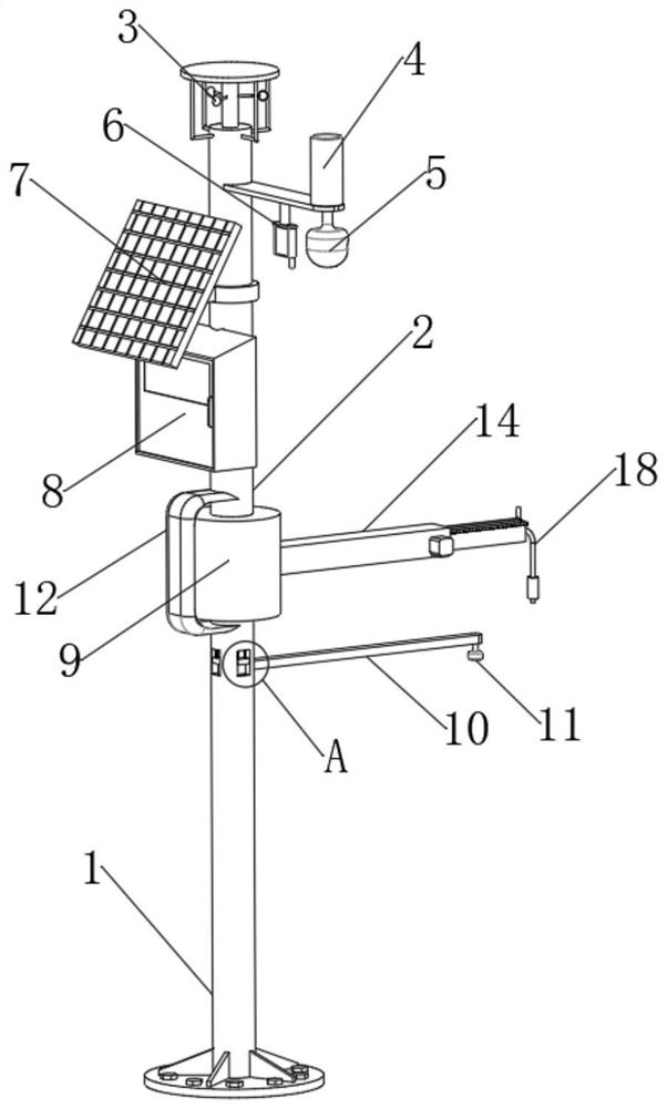
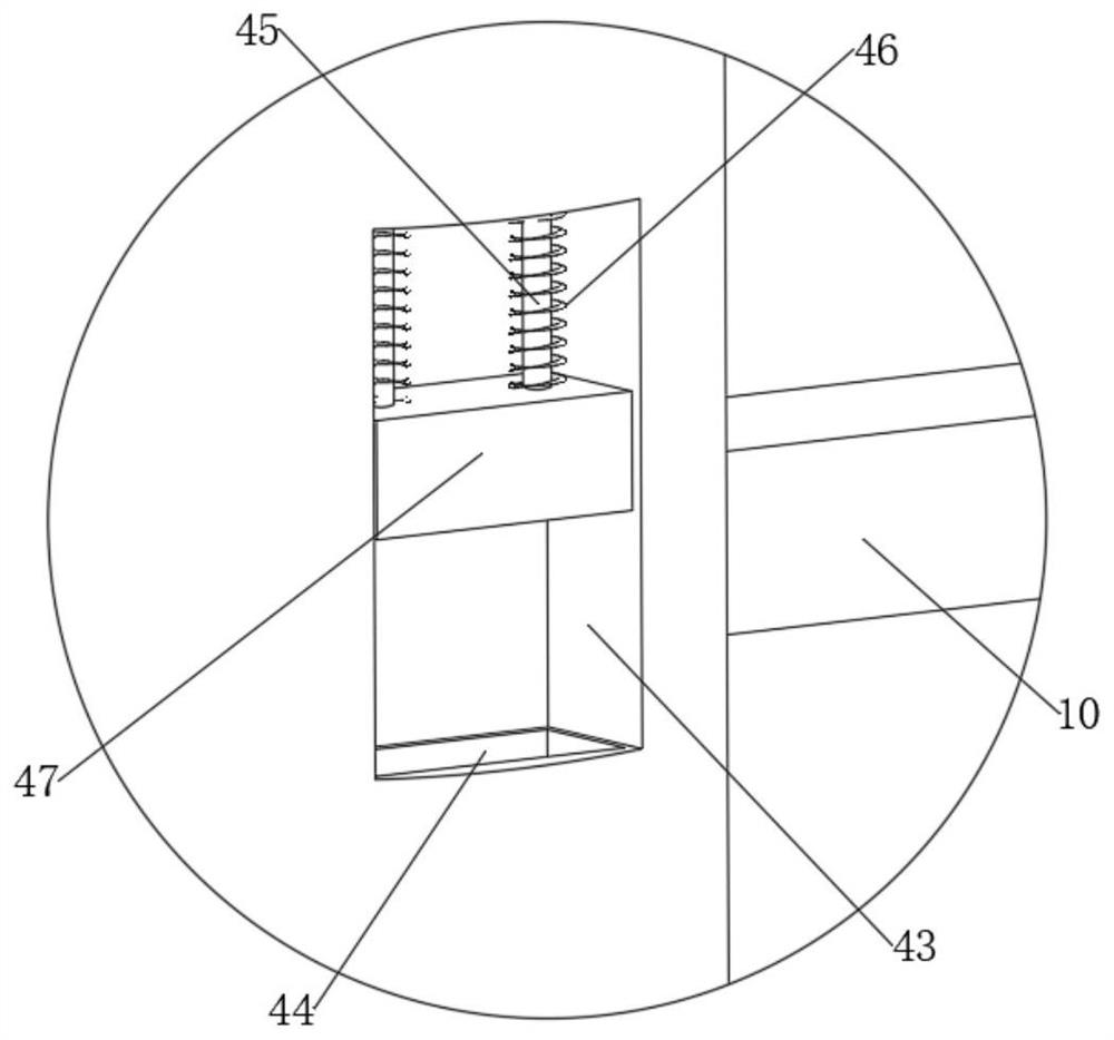
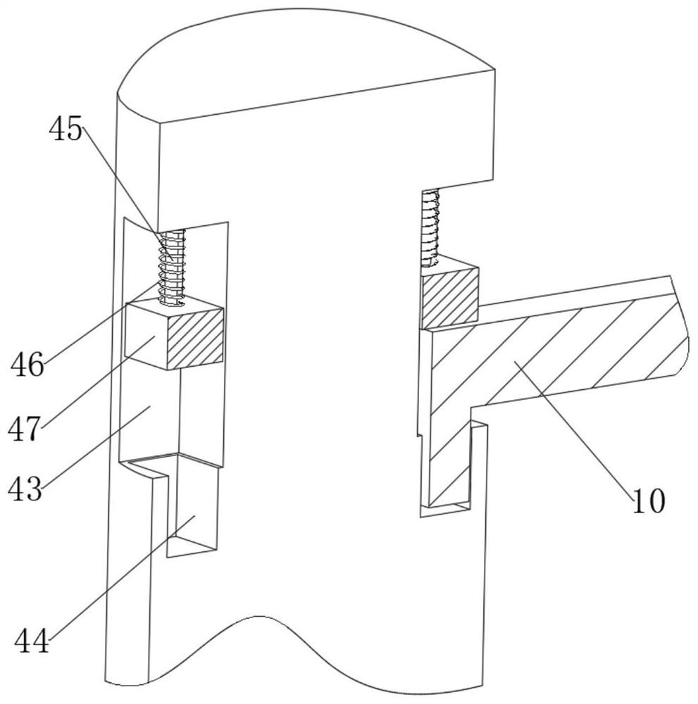
[0032] Depend on Figure 1-3 Given, the present invention includes a lower fixed rod 1, the upper end of the lower fixed rod 1 is fixedly connected with a fixed connecting rod 12, the upper end of the fixed connecting rod 12 is fixedly connected with an upper fixed rod 2, and between the upper fixed rod 2 and the lower fixed rod 1 A position adjustment mechanism 9 is arranged, a control box 8 is arranged on the side wall of the upper fixing rod 2, and a solar cell panel 7 is arranged above the control box 8. The 7-position solar panel provides power to the whole device. The upper end of the upper fixing rod 2 is provided with a wind direction and wind speed detection device 3, a rainfall cylinder 4, a monitoring device 5 and a temperature and humidity sensor 6. The temperature and humidity sensor 6 is RH11-PT100, using the upper fixing rod 2. The wind direction and wind speed detection device 3 at the upper end detects the wind speed and direction near the water surface, and a...


PUM


Abstract

The invention discloses a water conservancy automation information acquisition device, and relates to the technical field of water conservancy projects. The lower end of the upper fixing rod is rotationally connected with the upper side wall of the connecting cylinder, an adjusting motor is fixedly connected to the inner wall of the lower side of the connecting cylinder, the output end of the adjusting motor is fixedly connected with a connecting plate, a rotating sliding rod is fixedly connected to the upper end of the connecting plate, a limiting sliding groove is formed in the side wall of the rotating sliding rod, and a locking outer frame is slidably connected into the limiting sliding groove. The upper end of the rotating sliding rod penetrates through the lower side wall of the locking outer frame and is fixedly connected with a baffle, the inner wall of the lower side of the inner side of the locking outer frame is fixedly connected with a locking inner frame, and the upper surface of the locking inner frame and the upper surface of the locking outer frame are both fixedly connected with locking rods. An electric push rod is adjusted to drive a pipe barrel to move downwards, a locking outer frame and a locking inner frame are pushed to compress a supporting spring, and therefore a locking rod at the upper end of the locking inner frame is pulled out of a locking groove in the lower end of an upper fixing rod, and the locking outer frame is driven to rotate under the action of an adjusting motor.

Description

technical field [0001] The invention relates to the technical field of water conservancy engineering, in particular to a water conservancy automation information collection device. Background technique [0002] Water conservancy information collection mainly includes; water and rain data collection, wind speed and temperature data collection, drought (moisture) data collection, industrial conditions data collection and water quality quality testing. The data is transmitted to the management department through the control box on the upper side of the buoy for the management department to view; [0003] When testing water quality, it is often necessary to move the water quality sensor to different locations, so as to simultaneously detect and compare water quality at different depths and locations. During the process, the water quality sensor is put into the water. When the position of the water quality sensor needs to be moved, the transmission line needs to be manually put ...

Claims


Application Information

Patent Timeline
Patent Type & Authority Applications(China)
IPC IPC(8): G01D21/02G01D11/00G01D11/30G01N33/18G01W1/04H02J7/35
CPCG01D21/02G01D11/00G01D11/30G01N33/18G01W1/04H02J7/35Y02A20/152
Inventor 荆志铎
Owner UNIV OF JINAN
Learn More