Ink-jet recording head and ink-jet recording apparatus

A technology of inkjet recording and recording elements, which is applied in the direction of measuring devices, measuring devices, instruments, etc., and can solve problems such as difficult clocks

Inactive Publication Date: 2004-05-12
CANON KK
View PDF2 Cites 0 Cited by
  • Summary
  • Abstract
  • Description
  • Claims
  • Application Information

AI Technical Summary

Problems solved by technology

In particular, since the main body mechanism must pass a large current to the light emitting element for optical communication, and the driving element must be switched at high speed, it is difficult to transmit a clock for a head with speed-up and increased nozzles by light

Method used


Image

  • Ink-jet recording head and ink-jet recording apparatus
  • Ink-jet recording head and ink-jet recording apparatus
  • Ink-jet recording head and ink-jet recording apparatus

Examples


no. 1 example

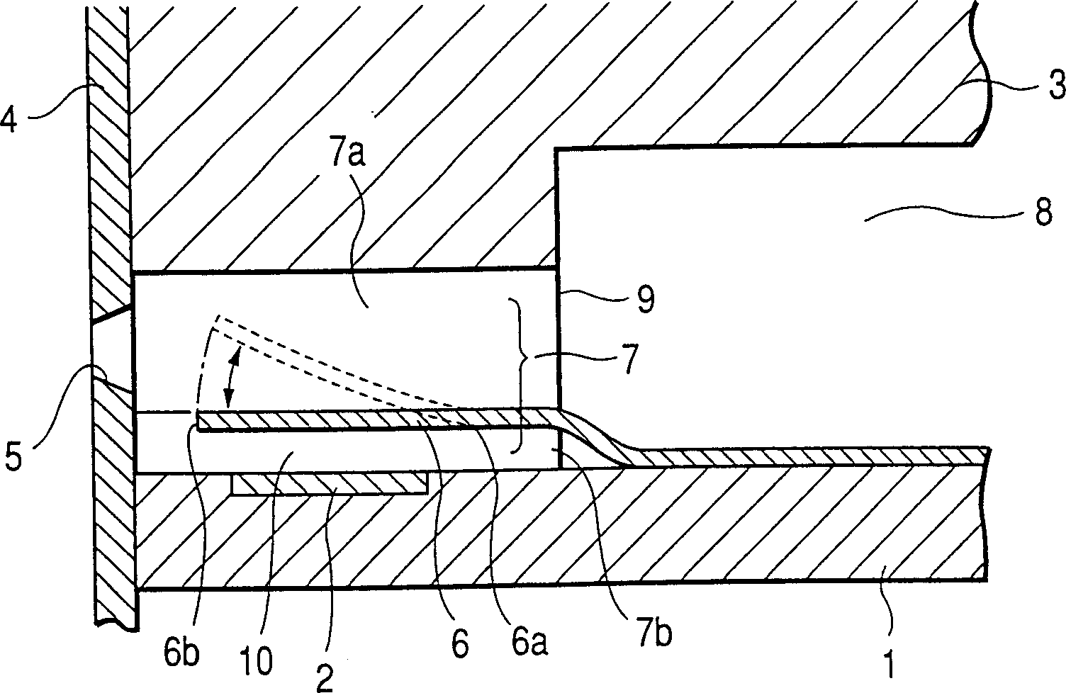
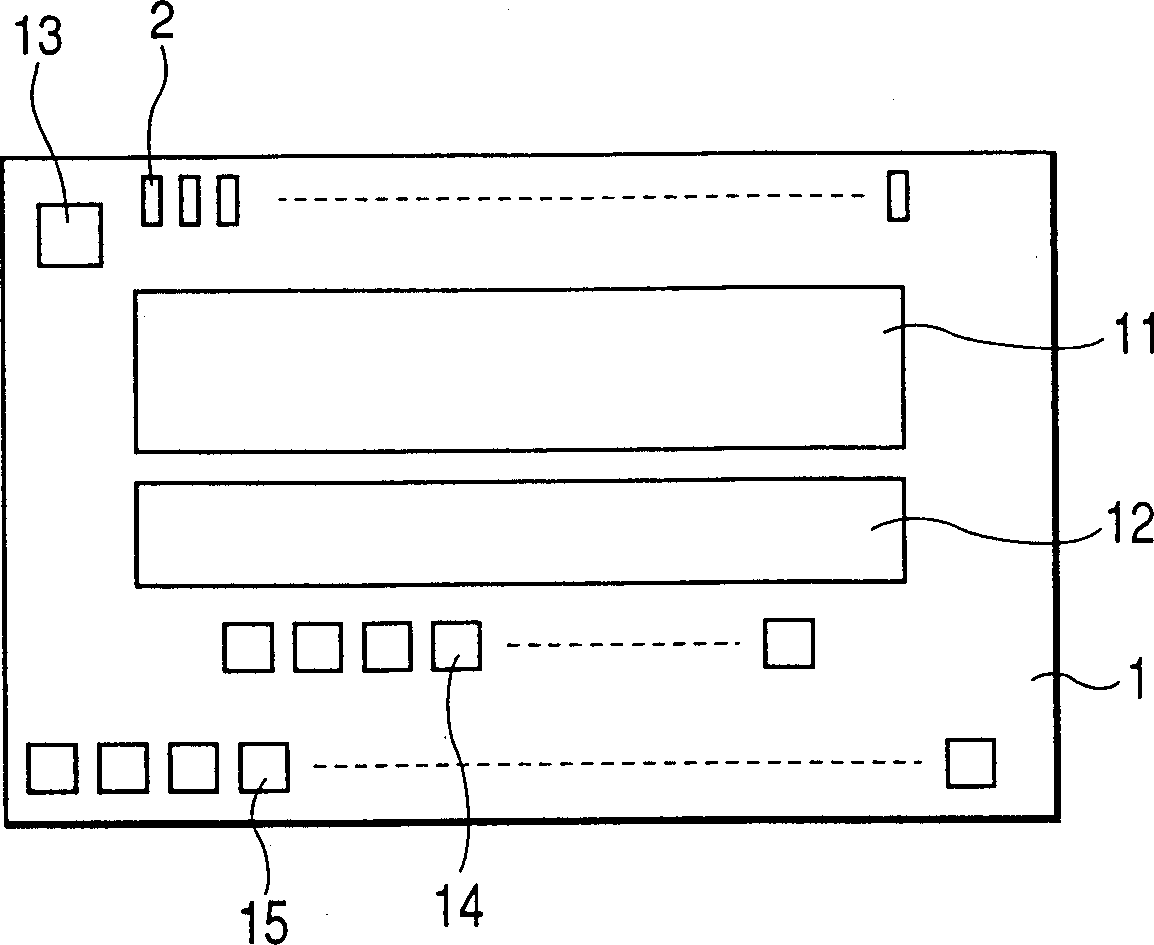
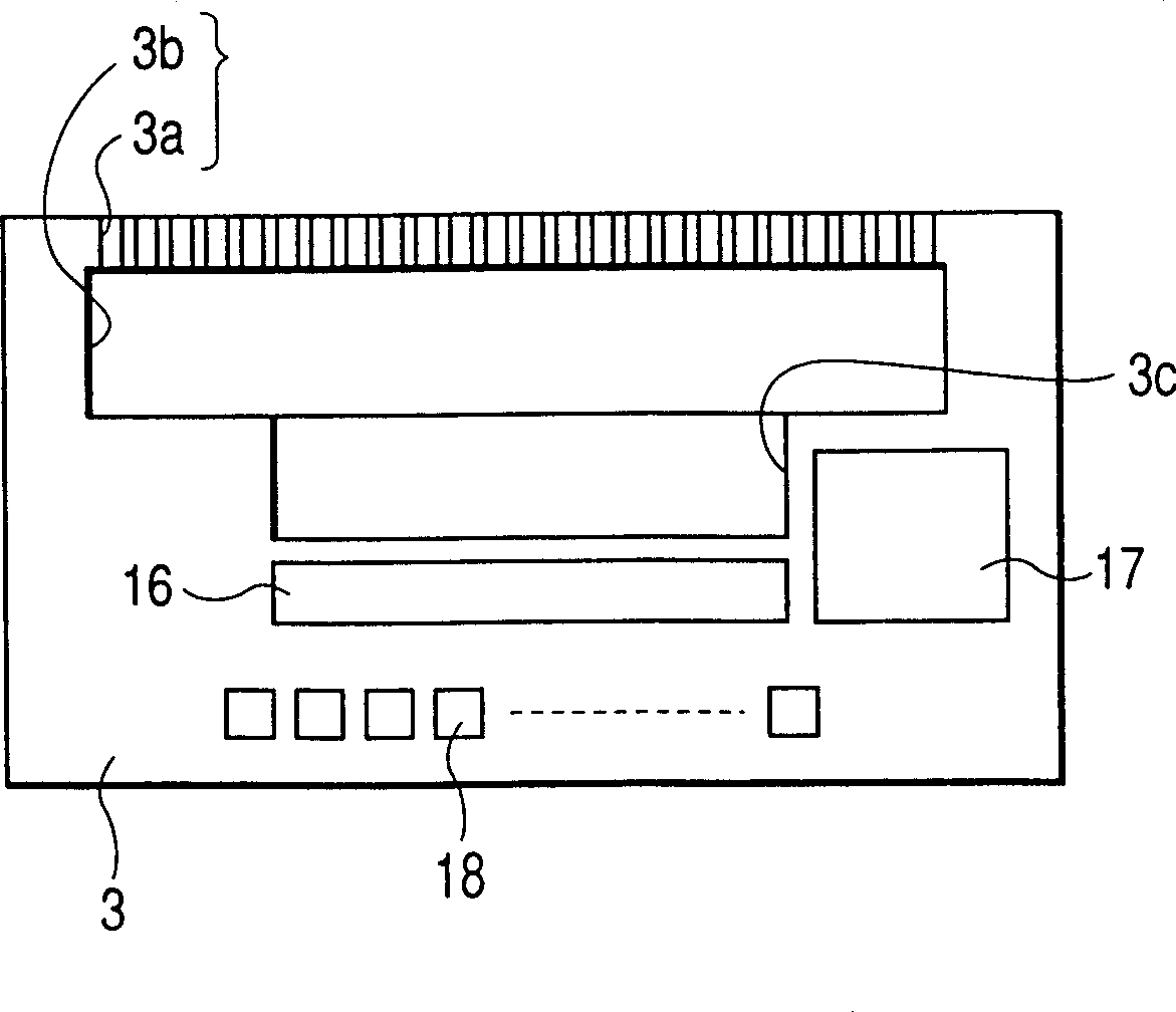
[0056] An ink jet recording head as a first embodiment usable in the present invention will be described below. The head has: a plurality of discharge orifices for discharging ink (liquid); a first substrate and a second substrate that are bonded together to form a plurality of liquid passages and are connected to the respective discharge orifices; A plurality of recording elements in each liquid channel are used to convert electrical energy into liquid discharge energy in the liquid channel; a plurality of functionally different elements or circuits are used to control the driving state of the recording elements. According to the function, these elements or circuits are assigned to a first substrate and a second substrate.

[0057] An example in which a heating element (heater) is used as a recording element will be described below, but a piezoelectric element that discharges ink by a piezoelectric effect may also be used for the recording element. figure 1 is a sectional v...

no. 2 example

[0140] Figure 8 is a signal flow diagram representing a second embodiment of the present invention.

[0141] omitted with Image 6 Description of the same section.

[0142] In this embodiment, in the enabling signal generator, the enabling signal is generated from the high resolution reference signal and the image data transfer signal. In this embodiment, since the activation signal does not need to be supplied from the outside, there can be produced an effect that the number of signal lines can be reduced. again Figure 8 In the above, the data transfer signal is used to obtain the heating pulse information, but the head can be added to include non-volatile memory such as EEPROM, and a structure for controlling the memory can be added. In addition, the high-resolution reference signal input to the activation signal generator does not have to be the same as the high-resolution reference signal input to the driving signal control circuit as long as they are synchronized wi...

no. 3 example

[0144] Figure 9 is a signal flow diagram showing a third embodiment of the present invention.

[0145] omitted with Image 6 Description of the same section.

[0146] In the second embodiment, the start signal is generated from the high-resolution reference signal and the image data transfer signal, however, in this embodiment, the start signal is generated from the reference input signal and the image before being input to the high-resolution reference signal generator Data transfer signal. Since the activation signal may have a small resolution relative to the heating signal, the raw reference input signal may be utilized without going through the high resolution reference signal generator relative to some heater drive control signals. Here, the structure of the enlarged CLK portion for calculating the high-resolution reference signal is disadvantageous when the resolution is reduced than necessary (since the circuit is also enlarged with larger calculated values), and i...


PUM


Abstract

There is disclosed an ink jet recording head comprises a plurality of recording elements for applying an energy to discharge ink, a recording element driver for driving the recording elements, a control circuit for controlling the recording element driver, and a high resolution reference signal generator using a plurality of input signals continuously given from the outside in a predetermined period and generating a reference signal which has a period shorter than the predetermined period, so that recording control is performed by supplying the reference signal to the control circuit. The bluntness of a pulse waveform by the transmission of the signal via a cable, and a radiation noise generated from the cable can be inhibited, and the ink jet recording head can cope with high speed and a multiplicity of nozzles.

Description

technical field [0001] The present invention relates to an ink jet recording head for discharging ink to form a recorded desired image on a material, and an ink jet recording apparatus. Background technique [0002] Hitherto, known inkjet recording methods include: application of heat and other energy to ink; state change causing rapid volume change in ink (generation of air bubbles); discharge of ink from a discharge orifice by force based on state change; ink adhesion Forming an image on a recording material is a so-called bubble jet recording method. A recording apparatus utilizing the bubble jet recording method, as described in U.S. Patent No. 4,723,129, generally has: a discharge orifice for discharging ink, an ink passage communicating with the discharge orifice, and an energy generating member located An electrothermal transducer for discharging ink in the ink channel. [0003] According to this recording method, a high-quality image can be recorded at high speed a...

Claims


Application Information

Patent Timeline
Patent Type & Authority Patents(China)
IPC IPC(8): B41J2/05
CPCB41J2/04563B41J2/04541B41J2/0458B41J2/04581B41J2/14048B41J2/04565B41J2002/14354B41J2/04591B41J2/04598
Inventor 今中良行山中昭弘久保田雅彦
Owner CANON KK
Why Eureka
Try Eureka