Electrolytic cleaning tank adopting polar plate polarity-unchanging middle conductor method

An electrolytic cleaning and intermediate conductor technology, applied in the electrolytic process, electrolytic components, etc., can solve the problems of limiting the cleaning efficiency and cleaning quality of electrolytic cleaning tanks, increasing the time for stopping production to process plates, and reducing the cleaning quality of strip steel, etc. Achieve the effects of solving the decline in strip cleaning quality, improving cleaning efficiency and cleaning quality, and solving the problem of stopping production and dealing with a large workload of plates

Active Publication Date: 2014-09-10
北京中冶设备研究设计总院有限公司
View PDF2 Cites 0 Cited by
  • Summary
  • Abstract
  • Description
  • Claims
  • Application Information

AI Technical Summary

Problems solved by technology

When this plate is in the anode state, a passivation layer will be produced and the voltage will rise, so at regular intervals, the polarity of the plate must be reversed to keep the cleaning tank working within the rated voltage
The main disadvantages of this type of electrolytic cleaning tank are: 1. Although the pole plates are regularly interchanged in polarity, there is still a passivation phenomenon on the plates, and the passivation speed is also accelerated with the increase of the current density. The improvement of the cleaning efficiency and cleaning quality of the cleaning tank also increases the time for stopping production to process the plates; 2. When the plate on the outlet side of the cleaning tank changes from cathode to anode, the strip passing through this area is the cathode. The oil and iron powder in the cleaning solution will be adsorbed on the surface of the strip, thereby reducing the cleaning quality of the strip

Method used


Image

  • Electrolytic cleaning tank adopting polar plate polarity-unchanging middle conductor method
  • Electrolytic cleaning tank adopting polar plate polarity-unchanging middle conductor method

Examples


Embodiment Construction

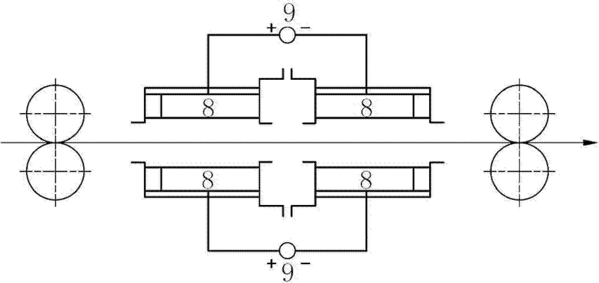
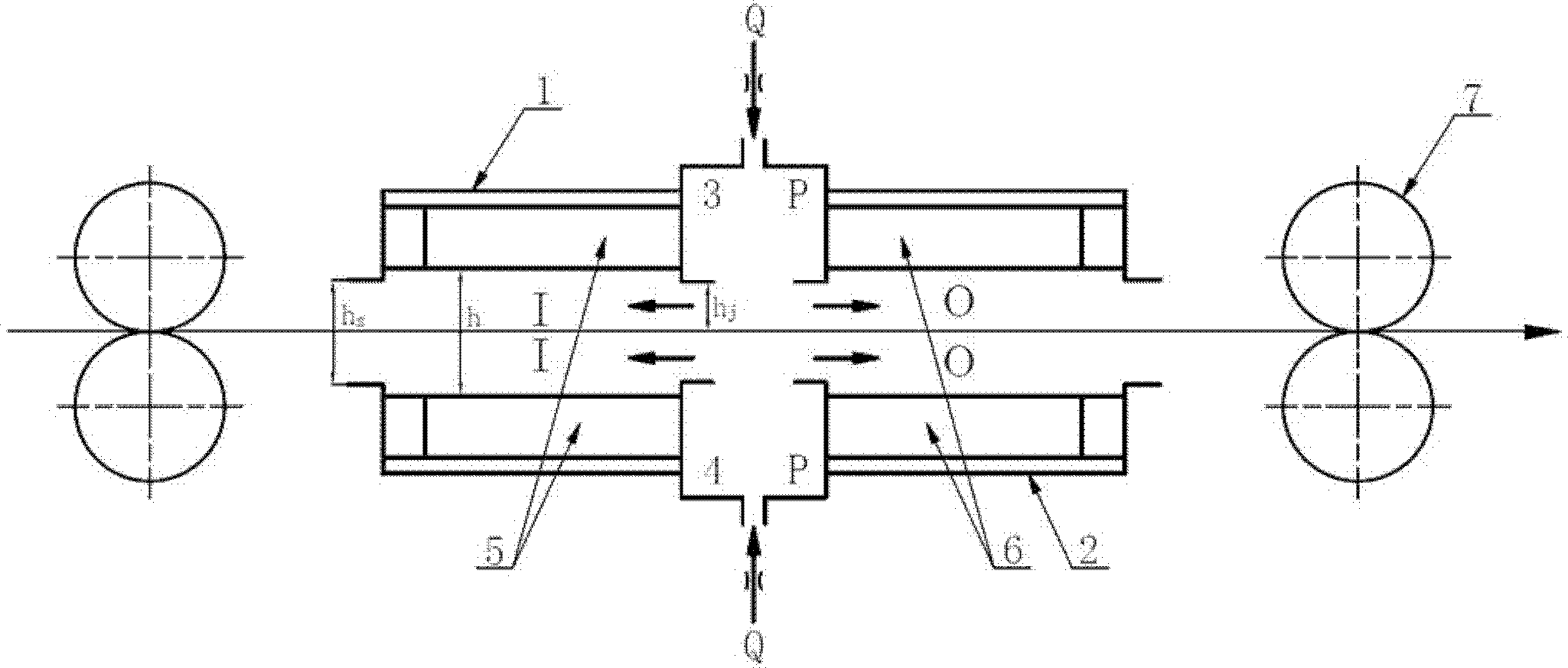
[0009] Embodiment of the present invention will be described in further detail below in conjunction with accompanying drawing: figure 2 The shown electrolytic cleaning tank adopts the method of not changing the polarity of the intermediate conductor on the pole plate. Its structure is mainly composed of upper tank body 1, lower tank body 2, upper static pressure chamber 3, lower static pressure chamber 4, anode plate 5, and cathode plate 6. Composed of squeeze rollers 7, the entrance cleaning area I is located from the entrance of the electrolytic cleaning tank to the left edge of the upper and lower static pressure chambers, and the outlet cleaning area O is located from the exit of the electrolytic cleaning tank to the right side of the upper and lower static pressure chambers edge; the height of the entrance and exit of the electrolytic cleaning tank is hs, and the value of hs is less than the distance h between the upper and lower electrode plates; hj. is the distance betw...


PUM


Abstract

The invention provides an electrolytic cleaning tank adopting a polar plate polarity-unchanging middle conductor method. The electrolytic cleaning tank mainly comprises an upper tank body, a lower tank body, an upper static pressure cavity, a lower static pressure cavity, an anode plate, a cathode plate and a drying roll. The height hs of an inlet and outlet of the electrolytic cleaning tank is smaller than the distance h between an upper polar plate and a lower polar plate; when the strip steel is centered, the distance between the edges of the static pressure cavities and the strip steel is hj, and the pressure of the upper static pressure cavity and the lower static pressure cavity is P; the flow rate of liquid flowing into the upper static pressure cavity and the lower static pressure cavity is Q; an inlet cleaning area I is arranged between the inlet of the electrolytic cleaning tank and the left edges of the upper static pressure cavity and the lower static pressure cavity; and an outlet cleaning area O is arranged between the outlet of the electrolytic cleaning tank and the right edges of the upper static pressure cavity and the lower static pressure cavity. The electrolytic cleaning tank is characterized in that the polar plate at the inlet side of the electrolytic cleaning tank is the anode, the polar plate at the outlet side is the cathode, and the polarity is not changed when the electrolytic cleaning tank is operated; and a titanium plate coated with an iridium oxide layer is adopted as the anode plate, and the cathode plate is made of stainless steel. The electrolytic cleaning tank disclosed by the invention has the effects of thoroughly solving the problem of passivation of polar plates, and having high cleaning efficiency and good quality.

Description

Technical field: [0001] The invention relates to the technical field of electrolytic cleaning, in particular to an electrolytic cleaning tank applicable to a strip steel continuous electroplating production line, a strip steel hot-dip galvanizing production line, a strip steel cleaning production line and a strip steel continuous annealing production line for electrolytic degreasing. Background technique: [0002] Existing electrolytic cleaning tanks for electrolytic degreasing of strip steel generally have three types of electrolytic degreasing methods, i.e. cathode method, anode method and intermediate conductor method, wherein the most widely used is the intermediate conductor method (such as figure 1 shown). The working principle of the intermediate conductor method is to let the strip pass through the cathode (or anode) area first, and then pass through the anode (or cathode) area. Under the action of the induced current, the strip steel is first cleaned as the anode (o...

Claims


Application Information

Patent Timeline
Patent Type & Authority Patents(China)
IPC IPC(8): C25F7/00
Inventor 翁祺于平高斌曹英龙郭小平王德祥
Owner 北京中冶设备研究设计总院有限公司
Why Eureka
Try Eureka