Mixed powder hot spraying method

A technology of mixing powder and thermal spraying, applied in spraying device, liquid spraying device, melt spraying and other directions, can solve the problems of wear and powder blocking, and achieve the effect of eliminating maintenance, prolonging life and low maintenance cost.

Inactive Publication Date: 2004-09-01
SUZUKI MOTOR CORP
View PDF1 Cites 0 Cited by
  • Summary
  • Abstract
  • Description
  • Claims
  • Application Information

AI Technical Summary

Problems solved by technology

[0013] According to the method of the present invention, the conveying powder and the powder particles melted by the plasma flow do not need to pass through the inner side of the positive electrode, therefore, the problem of the adhesion of the molten powder particles to the positive electrode and the powder blockage caused by the adhesion in the traditional technology is solved And the problem of wear in the powder conveying channel of the positive electrode

Method used


Image

  • Mixed powder hot spraying method
  • Mixed powder hot spraying method
  • Mixed powder hot spraying method

Examples


example 1

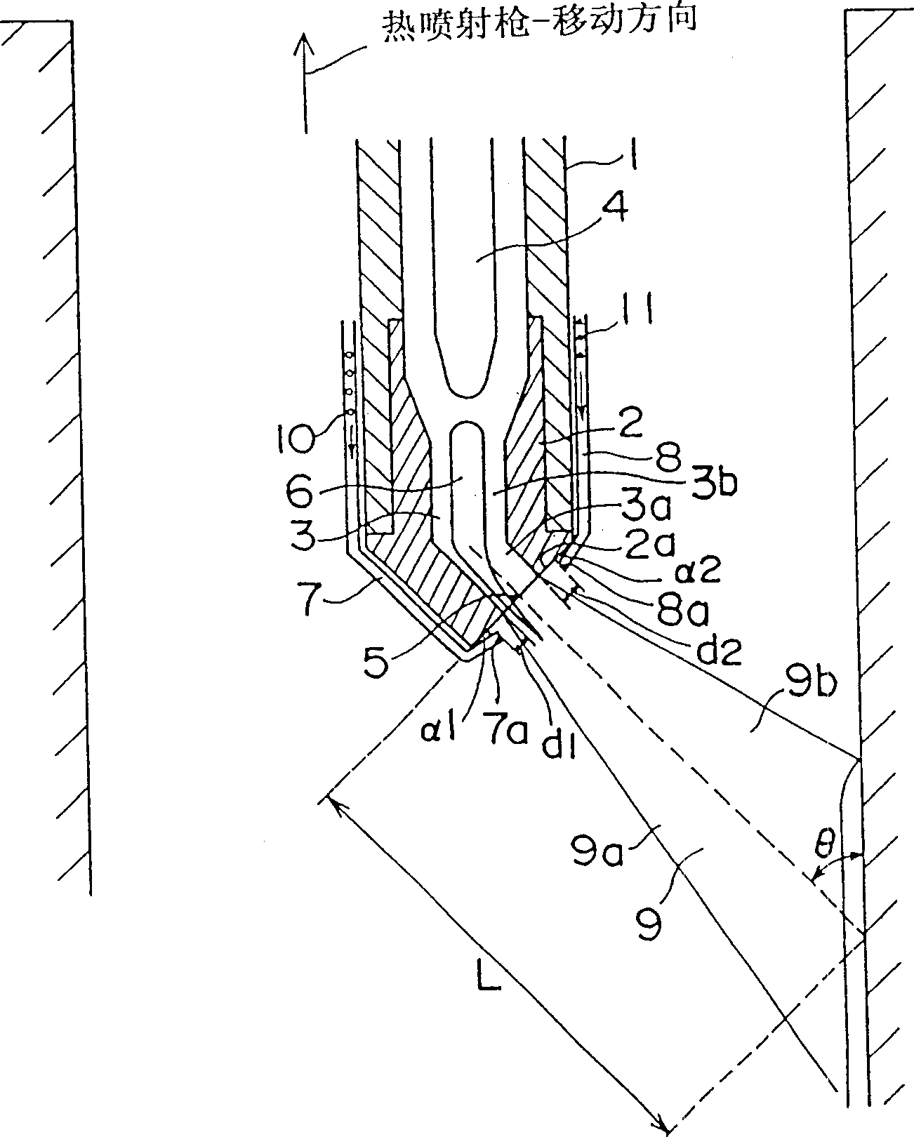
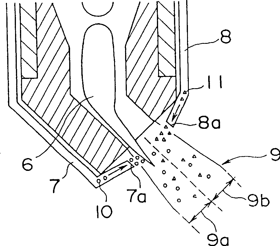
[0066] With two external delivery systems of the present invention ( figure 1 ) according to the conditions shown in Table 3 (conveyance ratio is 80% by weight of carbon steel powder (about 60% volume ratio)-20% by weight of Al-Si-based alloy powder (about 40 % volume ratio)) Carbon steel powder was fed from the high temperature portion 9a side of the thermal spray flame 9 and Al—Si based alloy powder was fed from the low temperature portion 9b side of the thermal spray flame 9, and continuous thermal spray experiments were performed. At this time, the distance d between the powder delivery port 7a on the high temperature portion 9a side of the thermal spray flame 9 and the plasma jet port 5 1 And the distance d between the powder delivery port 8a on the low temperature portion 9b side of the thermal jet flame 9 and the plasma jet jet port 5 2 respectively set as: d 1 = 2 mm, d 2 = 2 mm. Sample 1 was prepared under the same conditions.

[0067] table 3

[0068] ...

example 2

[0090] Use two external delivery systems of the present invention ( figure 1 ) cavity thermal spray gun and transport carbon steel powder from the high temperature 9a side of thermal spray flame 9 according to the conditions shown in Table 3, and transport Al-Si alloy-based powder from the low temperature 9b side of thermal spray flame 9 to carry out Continuous thermal spray experiments. In this case, set d 1 = 2 mm, d 2 = 2 mm.

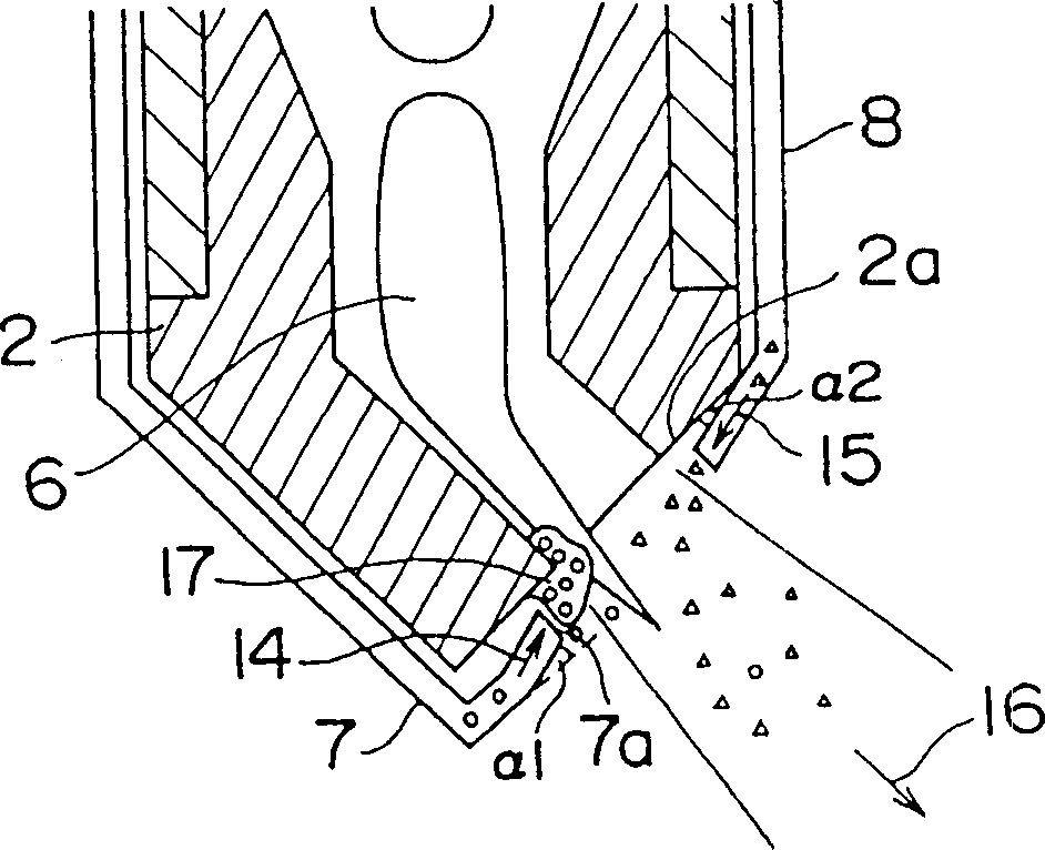
[0091] In Example 2-1, setting α 1 = -10°, α 2 = 0°, where α 1 =-10° means image 3 In the illustrated case of the direction 14 of powder injection from the high temperature 9a side of the thermal injection flame 9, the injection direction of the powder delivery port 7a is turned to the positive side and opposite to the forward injection direction 16, which is opposite the plasma jet injection surface 2b.

[0092] 40 minutes after the start of the continuous thermal spraying experiment, a wall 17 of molten carbon steel particles adhering to t...


PUM

PropertyMeasurementUnit
diameteraaaaaaaaaa

Abstract

A mixed powder thermal spraying method in which: a plasma jet is bent to carry out thermal spraying; in forming a mixed thermal spraying film comprising two kinds of materials having different melting points by bore thermal spraying, powder-feeding ports are provided for each material; and each powder-feeding port is controlled respectively to externally feed each material.

Description

technical field [0001] The present invention relates to a mixed powder thermal spraying method, more precisely, relates to a mixed powder thermal spraying method in which the plasma flow is bent for thermal spraying. Background technique [0002] This thermal spraying technology has been widely used in sliding parts of automobiles as a method of making its sliding surface wear-resistant. The range of materials used for thermal spraying can range from a single material to a mixture (or composite) depending on the conditions of use. materials in different fields. In these cases, when the inner surface of the bore of the cylinder is thermally sprayed with plasma, a plasma thermal spray gun is used to spray the bore; the structure of the plasma thermal spray gun includes: The flow bends to the direction of extension of the gun and performs thermal injection ( Figure 11 ) system, and a system according to the positive and negative poles ( Figure 12 ) is arranged so that the g...

Claims


Application Information

Patent Timeline
Patent Type & Authority Patents(China)
IPC IPC(8): B05D1/10B05B7/22B05D7/24C23C4/08C23C4/12C23C4/16
CPCC23C4/16C23C4/12C23C4/08
Inventor 高桥正志国冈诚也宫井研二
Owner SUZUKI MOTOR CORP
Why Eureka
Try Eureka