Hydraulic driver of internal combustion engine

An internal combustion engine and hydraulic technology, applied in valve devices, machines/engines, mechanical equipment, etc., can solve the problems of complex transmission, poor manufacturability, and high cost, and achieve the effects of flexible installation parts, easy electronic control, and simple structure

Inactive Publication Date: 2004-09-15
SOUTH CHINA UNIV OF TECH
View PDF1 Cites 0 Cited by
  • Summary
  • Abstract
  • Description
  • Claims
  • Application Information

AI Technical Summary

Problems solved by technology

[0002] In internal combustion engines, the traditional cam-driven valve device has disadvantages such as large driving impact, complicated transmission, poor workmanship, and difficulty in achieving an ideal lift curve.
The German FEV Engine Company adopted the electromagnetic valve solution, and the opening and closing of the starting valve is controlled by the electromagnetic valve. This solution puts forward extremely high requirements on the response of the electromagnetic valve, and the processing and manufacturing are difficult and the cost is high.
Chinese patent CN1250841A proposes a hydraulically driven valve device, each valve movement of which is controlled by a rotor, which requires a group of rotors with the same number of cylinders. The structure is relatively complicated and the volume is large, especially for multi-cylinder engines. so so

Method used


Image

  • Hydraulic driver of internal combustion engine
  • Hydraulic driver of internal combustion engine
  • Hydraulic driver of internal combustion engine

Examples


Embodiment Construction

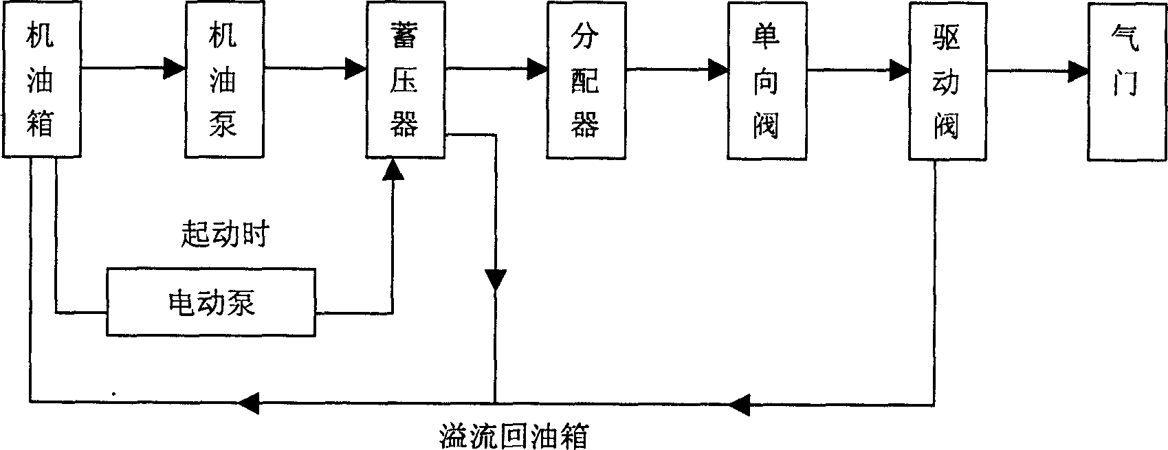
[0011] Such as figure 1 Shown, the specific work process of the present invention is: 1. machine oil is sent into pressure accumulator by electric pump (when starting) or machine oil pump (during normal operation); Through the mechanically driven timing distributor, the high-pressure oil is sent to the driving valve corresponding to a certain cylinder valve at a certain time, and lasts for a certain time; 3. Under the action of oil pressure, the driving valve overcomes the force of the spring and the force of the valve Under the pressure of the gas, the valve is driven according to a certain rule, so as to realize the opening and closing of the valve on time. A one-way valve is installed between the distributor and the drive valve to avoid backflow of high-pressure oil, excessive pressure loss and reduce system action hysteresis. The oil overflowing from the pressure accumulator, drive valve, etc. will flow back to the oil tank by itself.

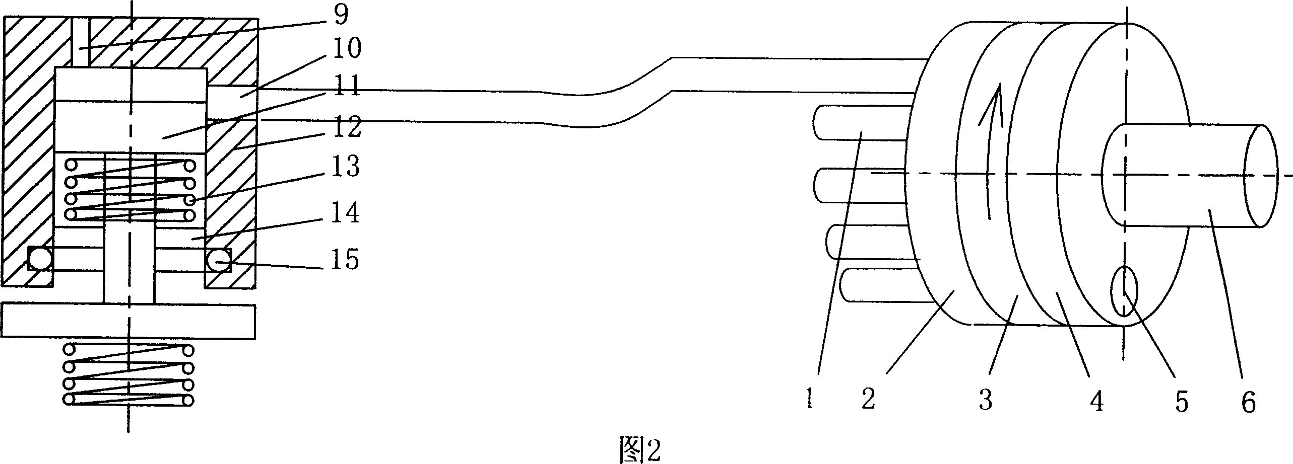
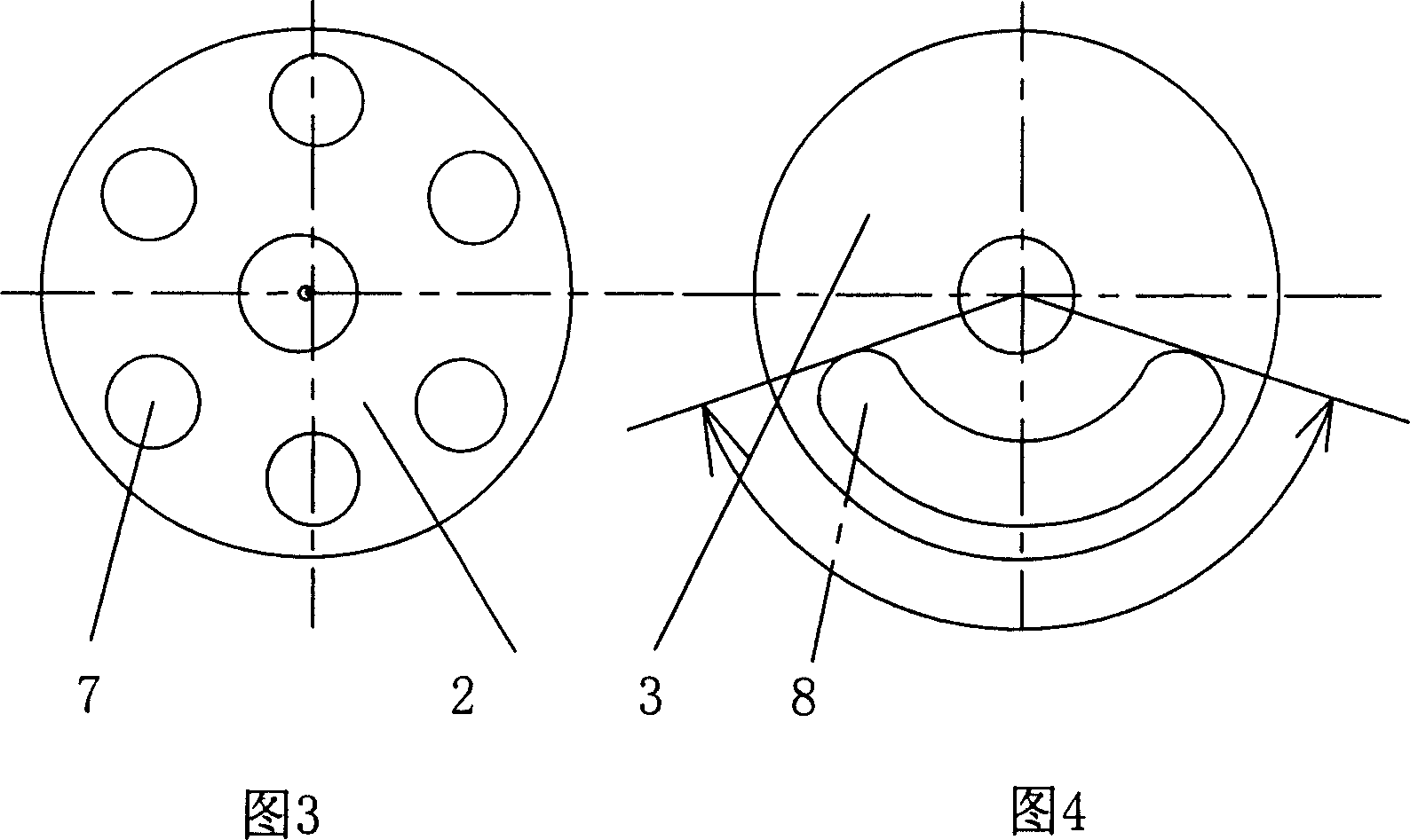
[0012] Shown in Fig. 2, 3, 4 is a ...


PUM


Abstract

The hydraulic driver of internal combustion engine consists of distributorand driving valve connected together, the distributor consists of moving disc, fixed disc, distributor hood, oil outlet pipe and rotating shaft connected together; and the valve consists of slide valve and guide tube connected together. Using the present invention for internal combustion engine makes the driver of the internal combustion engine impact-less flexible one and makes it possible to obtain satisfied lift rule through relatively simpler machining process dissimilar to that in cam driving mode. The present invention has the features of no side pressure, flexible part installing position, small size, simple structure, easy machining and easy electric control. The present invention is also suitable for other machines with air valve.

Description

(1) Technical field [0001] The invention relates to the technical field of internal combustion engines, in particular to a hydraulically driven valve device for internal combustion engines. (2) Background technology [0002] In the internal combustion engine, the traditional cam-driven valve device has disadvantages such as large driving impact, complicated transmission, poor workmanship, and difficulty in achieving an ideal lift curve. The German FEV Engine Company adopted the electromagnetic valve solution. The opening and closing of the starting valve is controlled by the electromagnetic valve. This solution puts forward extremely high requirements on the response of the electromagnetic valve, and the processing and manufacturing are difficult and the cost is high. Chinese patent CN1250841A proposes a hydraulically driven valve device, each valve movement of which is controlled by a rotor, which requires a group of rotors with the same number of cylinders. The structure i...

Claims


Application Information

Patent Timeline
Patent Type & Authority Patents(China)
IPC IPC(8): F01L13/04
Inventor 张勇
Owner SOUTH CHINA UNIV OF TECH
Why Eureka
Try Eureka