Check patentability & draft patents in minutes with Patsnap Eureka AI!

Sonic data logging system

A downhole tool and sound wave technology, which is used in the measurement of ultrasonic/sonic/infrasonic waves, boreholes/well components, seismology for logging records, etc., can solve problems such as low work efficiency and transmission errors

Inactive Publication Date: 2004-11-03
SCHLUMBERGER OVERSEAS SA
View PDF0 Cites 1 Cited by
  • Summary
  • Abstract
  • Description
  • Claims
  • Application Information

AI Technical Summary

Problems solved by technology

In addition, since data unnecessary for the sonic log analysis is also transmitted, the efficiency of the work is rather low
Moreover, because a large amount of digital data is transmitted through a long logging cable, there is also the problem of transmission error

Method used


Image

  • Sonic data logging system
  • Sonic data logging system
  • Sonic data logging system

Examples


Embodiment Construction

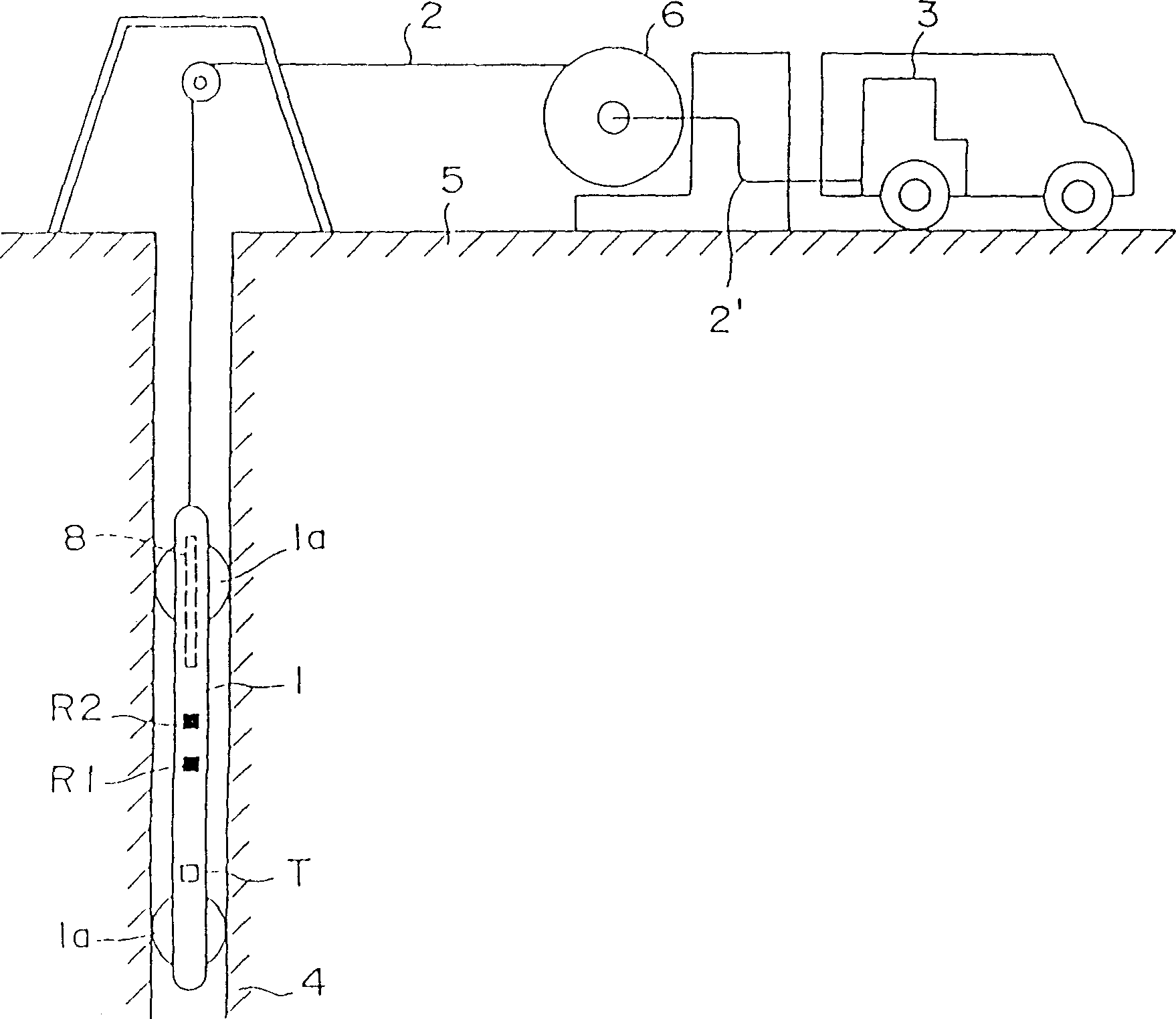
[0049] figure 1 It is a schematic diagram of an acoustic logging system constructed according to an embodiment of the present invention. Such as figure 1As shown, the acoustic logging system of the present invention includes a downhole tool (also called a detector) 1, which can move up and down in a wellbore 4 drilled in the formation. The downhole tool 1 is elongated, and an acoustic transmitter T is installed on the outer peripheral surface of its outer cover, and a pair of them are spaced apart from each other by a predetermined distance in the vertical direction, and are also spaced apart from the transmitter T by a predetermined distance in the vertical direction. distance to the receivers R1 and R2. A downhole processing device 8 is hermetically arranged in the outer cover of the downhole tool 1 . An example of a specific structure of the downhole processing device 8 will be described in detail later with reference to FIG. 3 . The downhole processing device 8 is conn...


PUM


Abstract

A sonic logging method with widest mode involves the pre-processing of a detection signal by a downhole processing device to simply determine the arrival time of a sonic signal at a receiver which is then transmitted to the surface. A suitable sonic logging downhole tool and system using it includes an A-D converter, a first memory, a second memory and a microprocessor.

Description

technical field [0001] The invention relates to a logging technology for measuring formation physical properties, in particular to a method and system for logging with acoustic waves. Background technique [0002] In order to explore underground resource layers, such as resources with oil and natural gas, the conventional method is to use logging technology to drill a well in the formation and set a measuring device called a downhole tool or detector into the well so that it can move up and down , using a processing device located at the surface connected to the downhole tool through the logging cable to process the signal measured by the downhole tool. In addition, sonic logging is also known which uses a sonic generator and a receiver located on a downhole tool to determine the velocity of sound waves propagating through the formation. See, for example, "Geophysical Well Logging," by Jay Tittaman, Academic Press, Inc., and "Illustrated Physical Exploration," Physical Expl...

Claims


Application Information

Patent Timeline
IPC IPC(8): E21B47/12E21B47/14G01H5/00G01V1/28G01V1/40G01V1/48
CPCG01V1/48
Inventor 福原政文莫里西奥·蒂加达
Owner SCHLUMBERGER OVERSEAS SA
Features
  • R&D
  • Intellectual Property
  • Life Sciences
  • Materials
  • Tech Scout
  • Unparalleled Data Quality
  • Higher Quality Content
  • 60% Fewer Hallucinations
Learn More