
Submerged dredging machine

A dredger and motor technology, which is applied in mechanically driven excavators/dredgers, earth movers/shovels, construction, etc., can solve the problems of large investment, high labor intensity of operators, inconvenient movement, etc. Wide range, good dredging effect and low labor intensity

Inactive Publication Date: 2004-11-10
ZHEJIANG JIALI TECH
View PDF0 Cites 1 Cited by
  • Summary
  • Abstract
  • Description
  • Claims
  • Application Information

AI Technical Summary

Problems solved by technology

Hydraulic dredgers usually use high-pressure water guns to scour the soil, and then transport the mud to the destination by the mud pump supported on the floating barrel. Its advantage is that it can transport mud for a long distance. The disadvantage is that it must be cut off, and the labor intensity of the operator is high. , can not deal with stone fixed objects, resulting in low efficiency
The dredger can berth at a designated position on the water surface, install the mud pump on the liftable bridge frame, twist the mud into mud with a reamer, and transport it to the destination after being sucked by the mud pump on the bridge frame. The distance is long, the disadvantage is that the excavation depth and angle of the lifting bridge arm are limited, and the investment is large, the cost of use is high, the movement is inconvenient, and it is not suitable for small rural rivers, etc.
Excavators are common equipment. During operation, the chassis is on the shore, and the excavating arm is extended into the water. Its advantage is high excavation efficiency. The disadvantage is that it must be used in conjunction with other transportation auxiliary equipment such as transport vehicles, and it is prone to secondary pollution, and the scope of operation is limited. , large investment, high cost of use
Furthermore, none of these dredging devices are suitable for deep water operations

Method used


Image

  • Submerged dredging machine
  • Submerged dredging machine

Examples


Embodiment Construction

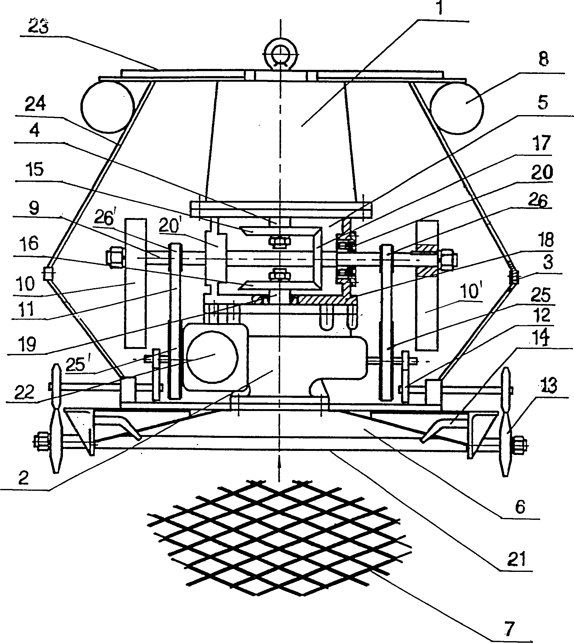
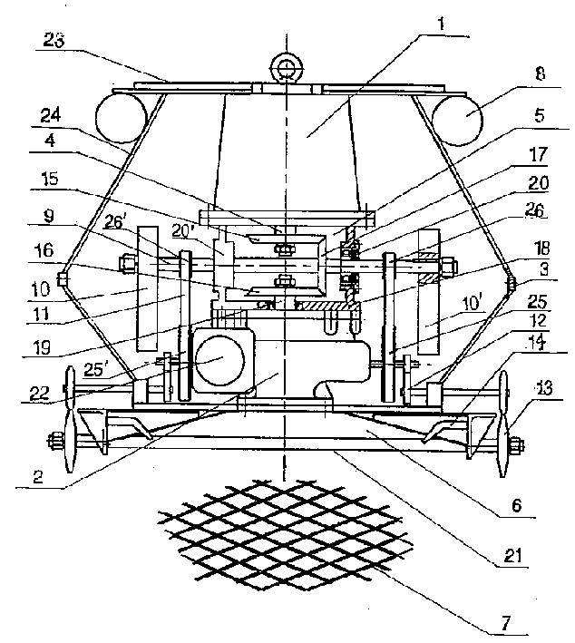
[0013] Such as figure 1 The shown submersible dredger includes an electric motor 1 , a mud pump 2 and a sealed housing 3 . The sealed housing 3 is tightly formed by the housing cover plate 23 , the housing wall 24 and the housing chassis 6 to provide a sealed space preventing water from entering. The electric motor 1 is fixed on the inner side of the housing cover plate 23, and its output shaft 4 passes through a speed change gearbox 5, and then outputs the power to the impeller shaft 19 of the mud pump 2 and the power shaft 9 perpendicular to the impeller shaft, and passes through The change of the gear ratio between the gears in the transmission gearbox 5 controls the rotating speed of the impeller shaft 19 and the power shaft 9 . The mud pump 2 is fixed on the housing chassis 6 , and the working surface 21 of the housing chassis is connected to the mud suction port of the mud pump 2 . The outside of the chassis working surface 21 is covered with a cutting screen 7, and th...


PUM


Abstract

The submersible river-desilting dredging machine is characterized by that its motor and mud pump are placed in a sealed shell body, the output shaft of said motor is connected with the mud pump by means of speed-changing gear box, and a power shaft which is perpendicular to the output shaft of motor is set between the motor and mud pump, the power shaft is matched with speed-changing gear box, and its two ends are equipped with symmetrical eccentric wheels, and the mud pump is placed on the chassis of the shell body, and the outer side of working surface of the chassis is covered with cutting filter screen, and the external end of sealed shell body is equipped with floating body. The invention is applicable to various river dredging engineerings.

Description

【Technical field】 [0001] The invention relates to a dredging device for dredging river channels for submerged operation. 【Background technique】 [0002] At present, the dredging devices for cleaning up riverbeds, ponds, artificial lakes and other silt debris mainly include hydraulic dredgers, dredgers and excavators. Hydraulic dredgers usually use high-pressure water guns to scour the soil, and then transport the mud to the destination by the mud pump supported on the floating barrel. Its advantage is that it can transport mud for a long distance. The disadvantage is that it must be cut off, and the labor intensity of the operator is high. , can not deal with stone fixed objects, resulting in low efficiency. The dredger can berth at a designated position on the water surface, install the mud pump on the liftable bridge frame, twist the mud into mud with a reamer, and transport it to the destination after being sucked by the mud pump on the bridge frame. The distance is lon...

Claims


Application Information

Patent Timeline
Patent Type & Authority Patents(China)
IPC IPC(8): E02F3/88E02F5/28
Inventor 龚政尧
Owner ZHEJIANG JIALI TECH
Learn More