

Elevator control device
A technology of elevator control device and power storage device, which is applied to circuit devices, battery circuit devices, current collectors, etc., can solve problems such as battery voltage rise, battery deterioration, gas generation, etc., and achieve the effect of suppressing deterioration.
- Summary
- Abstract
- Description
- Claims
- Application Information
AI Technical Summary
Problems solved by technology
Method used
Image

Examples
Embodiment Construction
[0041] Embodiment 1 will now be described.
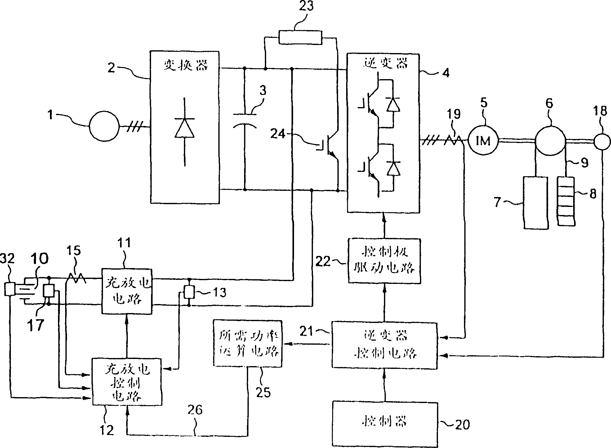
[0042] An elevator control device according to Embodiment 1 of the present invention will be described with reference to the drawings. figure 1 Shown is a configuration diagram of an elevator control device according to Embodiment 1 of the present invention. In addition, in each figure, the same code|symbol represents the same or a corresponding part.
[0043] exist figure 1 Among them, 1 is a power frequency three-phase AC power supply, 2 is a converter composed of diodes, etc., 3 is a capacitor, 4 is an inverter, 5 is an electric motor such as an induction motor, 6 is a traction machine, and 7 is an elevator car. 8 is a counterweight, and 9 is a traction wire rope.
[0044] The motor 5 rotates and drives the traction machine 6, so that the elevator car 7 and the counterweight 8 connected to the two ends of the traction wire rope 9 move, and the passengers in the car 7 are transported to a specified floor.
[0045] The conver...
PUM
 Abstract
Description
Claims
Application Information