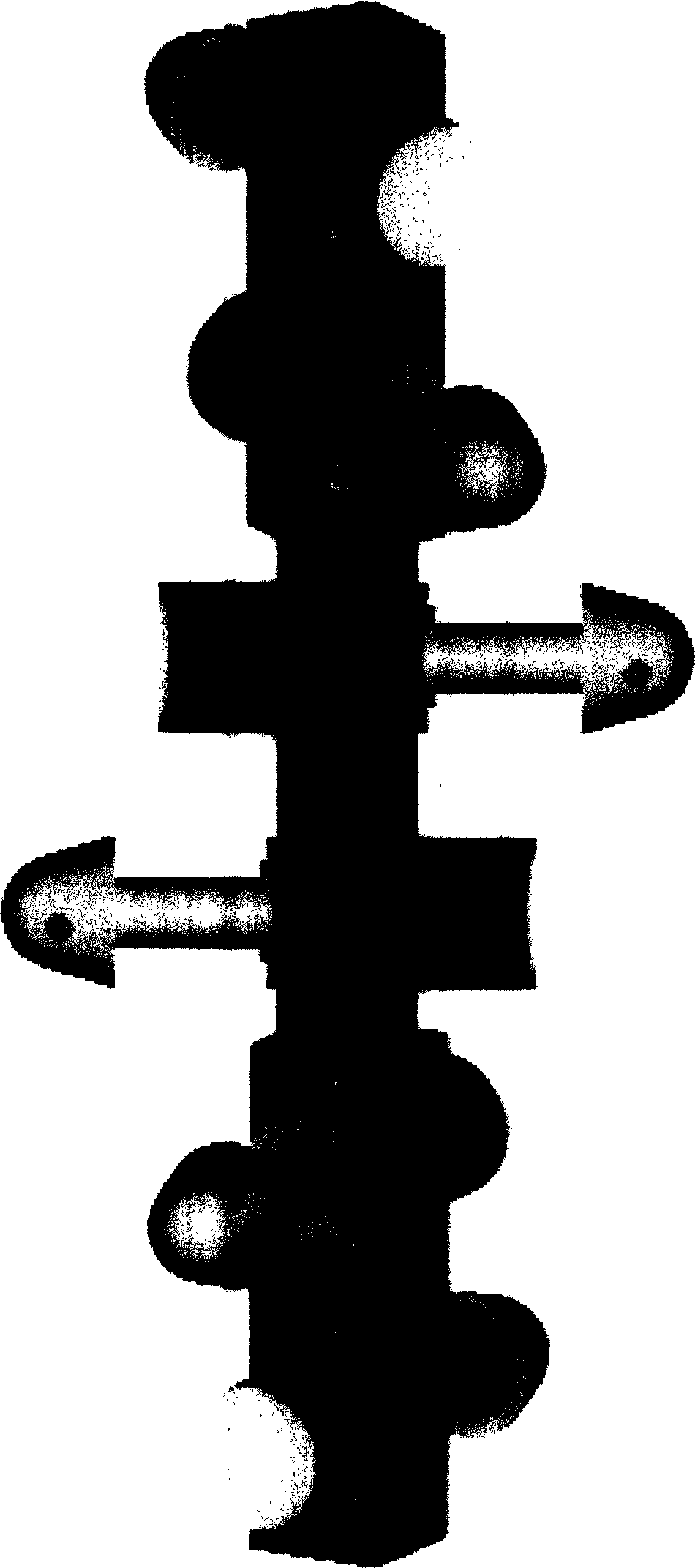
Spine-like bored concrete pile construction technique and extrusion shaping machine thereof

A technology of cast-in-situ piles and forming machines, which is applied to drilling equipment and methods, sheet pile walls, and earthwork drilling and mining, and can solve problems such as difficulty in ensuring construction quality, complicated construction operations, and low degree of automation, and achieve easy construction quality assurance , Facilitate automatic control, improve the effect of force mechanism

Inactive Publication Date: 2005-08-24
武维承 +1
View PDF0 Cites 0 Cited by
  • Summary
  • Abstract
  • Description
  • Claims
  • Application Information

AI Technical Summary

Problems solved by technology

[0010] The disadvantages of extruding and expanding multi-branch cast-in-situ piles are: (1) the equipment is huge and heavy; (2) extruding and expanding a supporting disc space requires the equipment to be transposed and the extruding and expanding process 10 times, and the construction operation is complicated, slow and automatic. (3) Only the first expansion of the space in the support plate is really compacted, and the degree of compaction in subsequent expansions is not ideal due to the scattered soil or soil dislocation, so the improvement of the bearing capacity is limited. (4) Squeeze-expanded cast-in-situ piles must be placed above pebbles, dense medium-coarse sand or other hard soil layers, otherwise they will not be squeezed in place, or the bearing capacity will not be significantly improved, which will be difficult for design and construction. Higher requirements are put forward; (5) Soil dislocation is easy to occur during extrusion and expansion in soft soil layers, and it is difficult to ensure the shape of the disc-shaped space; " phenomenon, which has a certain impact on normal construction; (7) due to repeated extrusion and expansion in a disc-shaped space and adjacent positions, the deflection of the disc cavity is relatively large, and the soil in the disc cavity is easy to fall, which not only increases the cost of cleaning scum workload, and it is difficult to guarantee the quality of construction

Method used

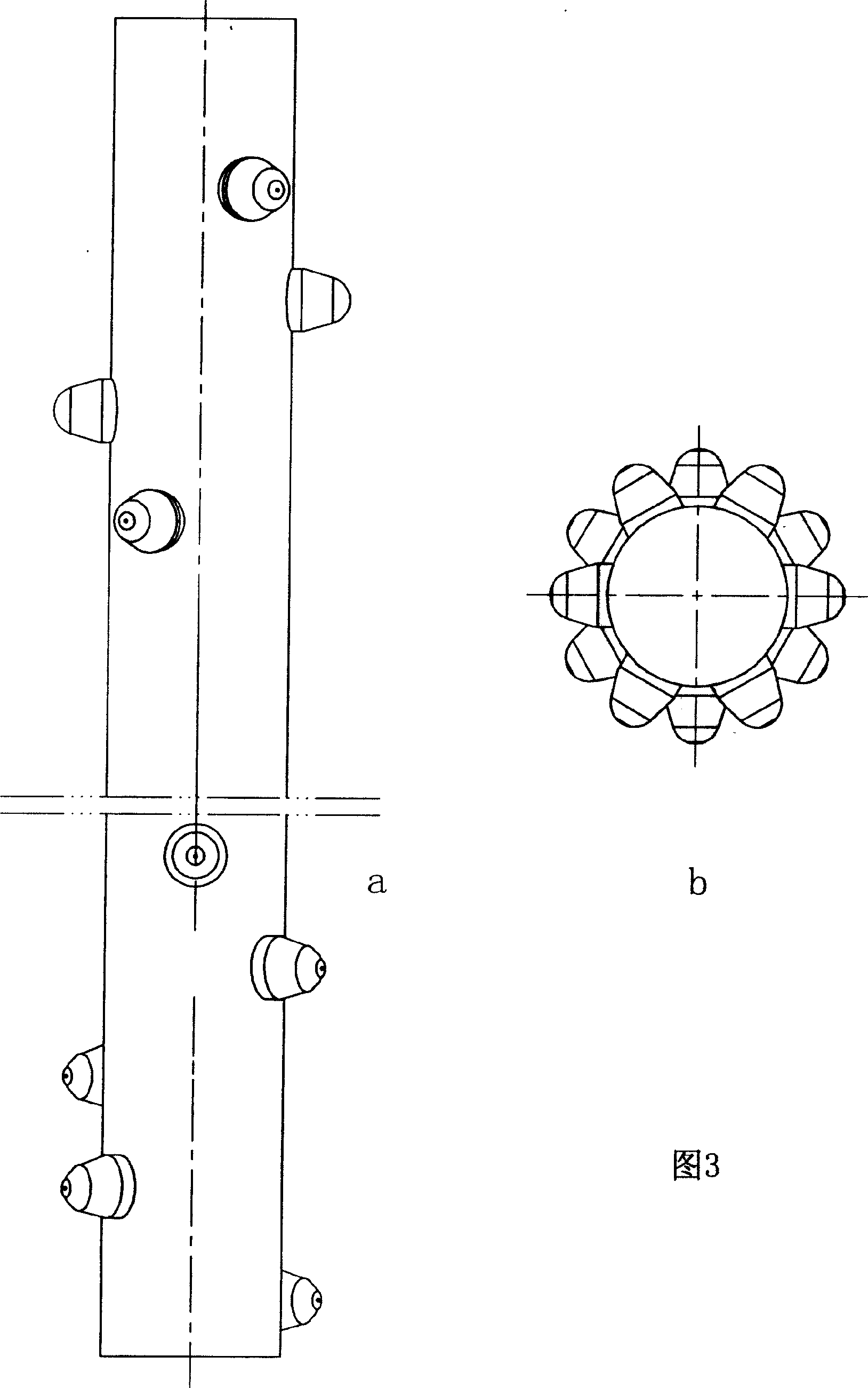

Image

  • Spine-like bored concrete pile construction technique and extrusion shaping machine thereof
  • Spine-like bored concrete pile construction technique and extrusion shaping machine thereof
  • Spine-like bored concrete pile construction technique and extrusion shaping machine thereof

Examples


Embodiment Construction

[0045] The invention has strong adaptability, can be used for pile hole construction under different geological conditions, and is suitable for operations such as mud retaining wall forming, dry operation drilling and cement grouting retaining wall forming. Now take the mud retaining wall forming as an example to further Embodiments of this invention will be described.

[0046] 1 Holes in mud retaining walls

[0047] like Figure 8 As shown in -A, first make the pile drilling machine at the fixed pile position, adjust the verticality, bury the casing, and start drilling. When the groundwater level is high, use the cohesive soil in the strata in the hole to make slurry with mud to protect the wall and form the hole. When the groundwater level is low, clean water can be injected to make slurry, and the specific gravity of the slurry discharged from the orifice is between 1.1 and 1.2. When passing through the soft soil layer or the easily collapsed soil layer, it is necessary ...


PUM


Abstract

The invention is a kind of acantha pouring stake constructing technology and the forming machine, it provides a new stake shape and the constructing device. The stake is distributed with acanthas all around; the stake end resistance pressure are increased greatly, the stake side resistance pressure are increased too, thus it changes the stress mechanism of stake body, upgrades the bearing ability of stake. The forming machine is made up of six special hydraulic cylinder and the end cap; two cylinders makes up a group, they are combined up and down, and placed in reversal; three groups of hydraulic cylinder are place transversely with 60 degrees, and they are connected with bolt. When in work, the forming machine are operated, the piston pole extrudes out, the end cap squeezes the stake hole wall, it can squeeze out six acanthas spaces; adjusts the position vertically, and repeats the squeezing action, thus there will has many stake acanthas spaces. Cleans the hole ad puts down the bar cage, and pours the concrete and gets the stake.

Description

Technical field [0001] This patent relates to building foundation construction technology, production and application technology of mechanical equipment. Background technique [0002] With the gradual increase of construction projects such as high-rises, bridges and other large-scale facilities, various deep-hole cast-in-situ piles have been widely used. At present, the commonly used cast-in-place piles are straight-hole cast-in-place piles (abbreviated as straight-hole piles or bored piles), and later gradually invented the expanded-bottomed cast-in-place piles (abbreviated as expanded-bottom piles) and squeezed and expanded multi-branched cast-in-place piles (abbreviated as branched piles). ). [0003] 1 straight hole cast-in-place pile [0004] Straight hole cast-in-situ piles were born in the 1940s. Compared with prefabricated piles, cast-in-situ piles with straight holes have obvious advantages in engineering design, engineering construction and engineering cost. Wi...

Claims


Application Information

Patent Timeline
Patent Type & Authority Patents(China)
IPC IPC(8): E02D5/36E02D5/48E21B7/28
Inventor 武维承武熙
Owner 武维承
Why Eureka
Try Eureka