Cathode-ray tube

A technology of cathode ray tube and shadow mask, applied in the frame field of color cathode ray tube, can solve the problems of color impurity and the like

Inactive Publication Date: 2005-10-05
LG PHILIPS DISPLAY KOREA CO LTD
View PDF0 Cites 0 Cited by
  • Summary
  • Abstract
  • Description
  • Claims
  • Application Information

AI Technical Summary

Problems solved by technology

[0038] Therefore, due to the above-mentioned problems, the relative positions of the fluorescent surface 40 within the shadow mask 70 and the screen 10 are changed, so that problems such as color impurity may occur.

Method used


Image

  • Cathode-ray tube
  • Cathode-ray tube
  • Cathode-ray tube

Examples


Embodiment Construction

[0052] Preferred embodiments of the present invention will now be described in detail with reference to the accompanying drawings.

[0053] Those parts that are the same as those of the conventional art will be assigned the same reference numerals, and explanations about them will be omitted.

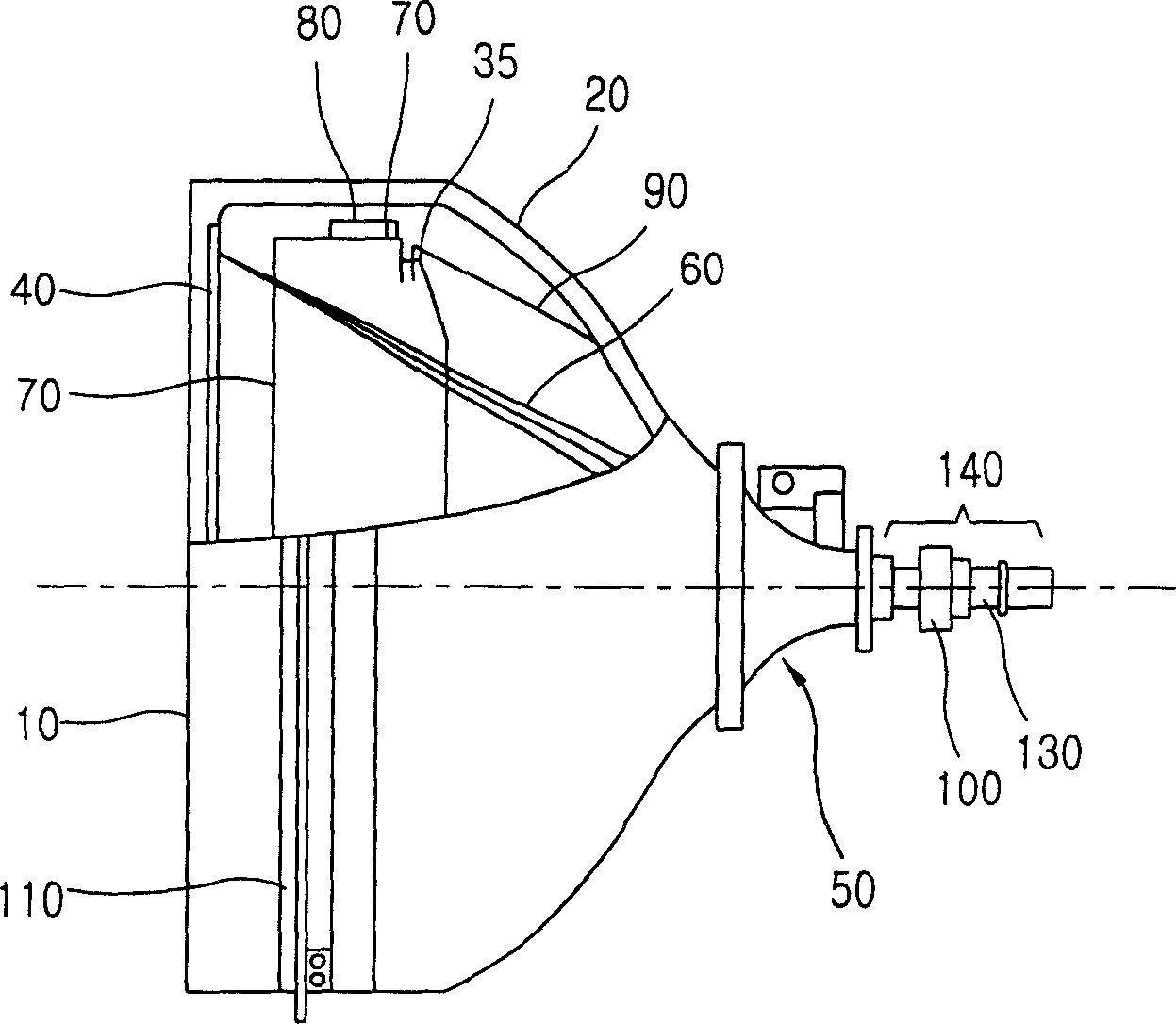
[0054] The present invention relates to a CRT capable of increasing the amount of compression without additional heat treatment for increasing the strength of the frame material, utilizing the frame by setting the range of the deflection length before and after mounting the shadow mask to the shadow mask assembly The material's own elasticity applies a tension to the mask, thereby increasing the tensor applied to the mask.

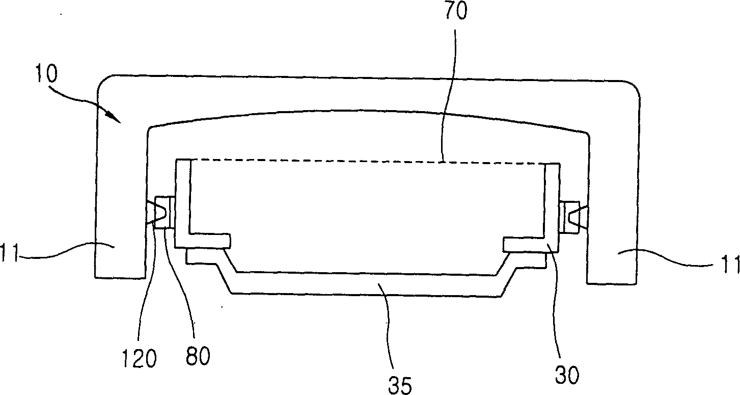
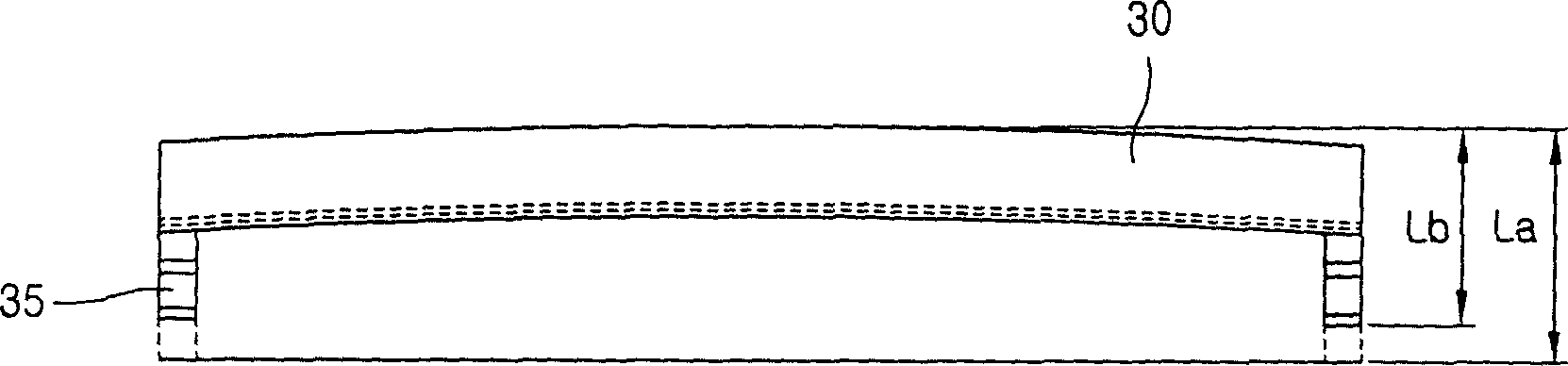
[0055] According to the present invention Figure 3A , 3B and 3C, before the shadow mask 70 is installed into the shadow mask assembly, the minimum distance between the extension plane of the upper surface of the main frame 30 and the extension plane of the lower s...


PUM


Abstract

A Cathode Ray Tube (hereinafter, CRT), includes a mask assembly which is composed of a main frame for supporting the shadow mask and a sub frame for supporting the main frame. When the minimum distance between the flat surface extended from the upper surface of the main frame and the flat surface extended from the lower surface of the sub frame is Lb, the height of the sub frame is Ls and the minimum distance between the flat surface extended from the upper surface of the main frame and the flat surface extended from the lower surface of the sub frame, in case the mask is attached to the mask assembly, is La, the following equation, 0.40<=Ls / Lb<=0.55 or 0.45<=(Ls-Lm) / Lb<=0.59 is satisfied and after compression, the following equation, 0.08<=(La-Lb) / (Lb-Lm)<=0.17 is satisfied. Therefore, the creep phenomenon, causing tension degradation and wrinkles at the corner portion of the shadow mask after the heat processing, can be prevented and the howling phenomenon, which can cause serious degradation of quality of screens by vibration of the CRT, can be prevented, considering the instrumental formality with a panel at the same time.

Description

field of invention [0001] The present invention relates to a cathode ray tube (hereinafter also written as CRT), and in particular to a frame of a color cathode ray tube capable of preventing the creep phenomenon caused by the tension drop and heat treatment steps and the microphonic phenomenon of the cathode ray tube . Background technique [0002] Typically, a color CRT with a flat screen, such as figure 1 As shown, it is composed of a front glass called a screen 10 and a rear glass called a funnel 20, and they are bonded to each other, and the inside is a high vacuum after sealing. [0003] Inside the CRT, a phosphor layer 40 is formed on the inner surface of the panel 10 as a predetermined light emitting material. The electron gun 130 is used for electron beam scanning, and the electron beam is emitted to the fluorescent surface 40 . The shadow mask 70 is used to sort colors so that the electron beams 60 generated in the electron gun 130 are irradiated to a predetermi...

Claims


Application Information

Patent Timeline
Patent Type & Authority Patents(China)
IPC IPC(8): H01J29/02H01J9/236H01J29/07H01J29/80
CPCH01J29/07H01J2229/0722H01J29/02
Inventor 金星勋郑京缜黄仁赫
Owner LG PHILIPS DISPLAY KOREA CO LTD
Why Eureka
Try Eureka