Solid luminous device packaged radiating member and its making method

A light-emitting device and manufacturing method technology, applied in semiconductor/solid-state device components, electric solid-state devices, cooling/ventilation/heating transformation, etc., can solve the problems of optical design heat dissipation, high labor-intensive, bulky packaging, etc.

Inactive Publication Date: 2005-10-19
OPTO TECH
View PDF0 Cites 1 Cited by
  • Summary
  • Abstract
  • Description
  • Claims
  • Application Information

AI Technical Summary

Problems solved by technology

However, the structure of the cluster not only requires extremely labor-intensive assembly, but also produces a very large package, which leads to problems related to optical design and heat dissipation.

Method used


Image

  • Solid luminous device packaged radiating member and its making method
  • Solid luminous device packaged radiating member and its making method
  • Solid luminous device packaged radiating member and its making method

Examples


Embodiment Construction

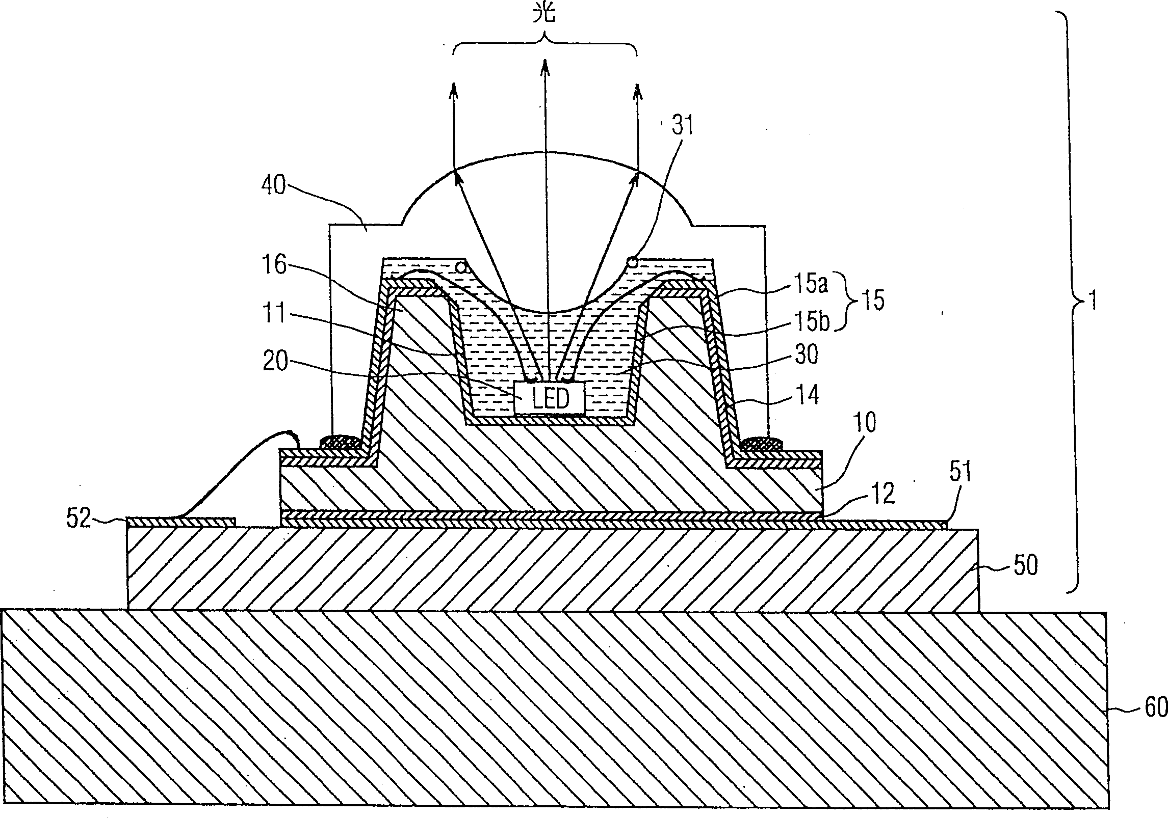
[0023] In the following description of the preferred embodiments, reference is made to figure 1 , illustrating a solid-state light emitting device package 1 with a heat dissipation member according to a first embodiment of the present invention.

[0024] The solid state light emitting device package 1 includes a metal substrate 10 , at least one LED chip 20 , an electrically insulating cooling liquid 30 , a transparent cover 40 , and a printed circuit board (PCB) 50 .

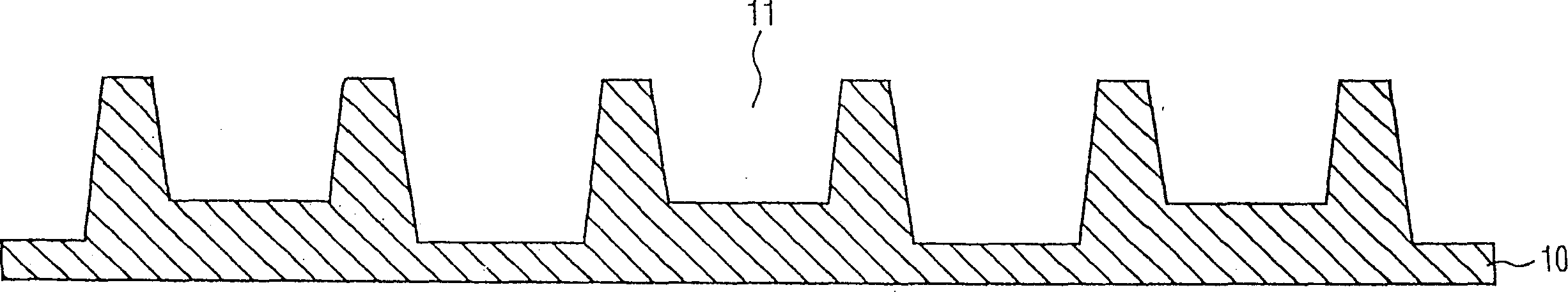
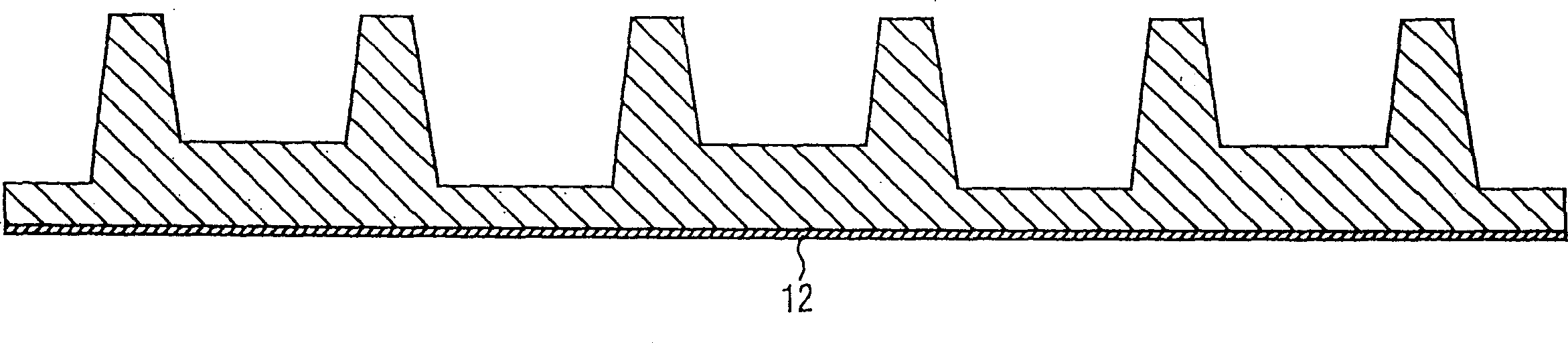
[0025] The metal substrate 10, which is preferably made of a material having excellent thermal conductivity such as aluminum, copper, etc., is formed with an upstanding wall portion 16 on one surface thereof, so that the surface of the metal substrate 10 will be formed as a cup-shaped portion 11. . Moreover, on the other surface of the metal substrate 10 opposite to the cup-shaped portion 11, there is a metal solder layer 12 such as copper, silver, or gold for connecting to the electrode 51 of the PCB 50, and ...


PUM


Abstract

LED with radiation structure and its manufacturing method characterizes in that a radiation electric isoaltion cooling liquid is filled in a closed container with a metal baseplate mounted with a LEDchip. The radiation forms rertical metal sidewall on it supporting a transparent cover over the closed container and surrounding at least one adjacent LED chip so as to make the generated Joule heat to expand to the vertical sidewall quickly through the said cooling liquid downward to the metal baseplate connecting to an extremetly external radiator to avoid overheat to the LED.

Description

technical field [0001] The present invention relates to a heat dissipation member for light emitting diodes (LEDs), especially LEDs that can be operated at extremely high driving currents, so that in applications that require extremely high brightness, the required brightness can be stably emitted. Background technique [0002] A light-emitting diode (LED), as it literally means, is a light-emitting device composed of semiconductor p-n junction diodes. Recently, LEDs have been applied only as instrument indicators or display signals thereof whose low brightness does not cause adverse effects. For example, it is used in applications such as power On / Off indicators in television (TV) systems, or digital display signals on clocks and electronic panels, where the brightness is only for the naked eye to distinguish at a very short distance. And its power consumption is extremely small, and its heat dissipation effect does not need to be considered. [0003] However, due to rece...

Claims


Application Information

Patent Timeline
Patent Type & Authority Patents(China)
IPC IPC(8): H01L23/34H01L33/64H05K7/20
CPCH01L24/97H01L2924/0002H01L2224/48091H01L2224/73265
Inventor 谢正雄颜志远洪建成彭美雪
Owner OPTO TECH
Why Eureka
Try Eureka