Method for operating offset press and its control device, offset press and offset printing material

A technology for offset printing presses and offset printing plates, which is applied to general parts of printing machinery, printing presses, measuring devices, etc., and can solve problems such as insufficient ink and excessive wetting.

Inactive Publication Date: 2006-05-24
COMMONWEALTH SCI & IND RES ORG
View PDF6 Cites 0 Cited by
  • Summary
  • Abstract
  • Description
  • Claims
  • Application Information

AI Technical Summary

Problems solved by technology

[0012] When a decrease in ink density is measured (on a plate, overlay, or paper), none of the prior art is able to determine whether this is the result of insufficient ink or overwetting (i.e., too much water resulting in excessive emulsification)

Method used


Image

  • Method for operating offset press and its control device, offset press and offset printing material
  • Method for operating offset press and its control device, offset press and offset printing material
  • Method for operating offset press and its control device, offset press and offset printing material

Examples


Embodiment Construction

[0087] measuring instrument

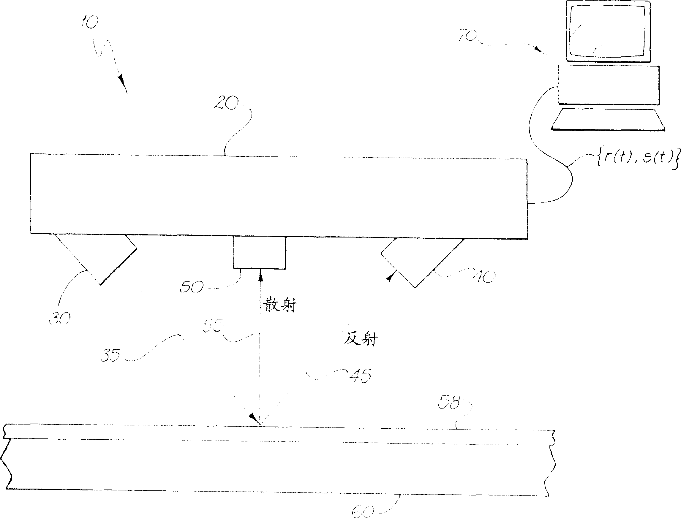
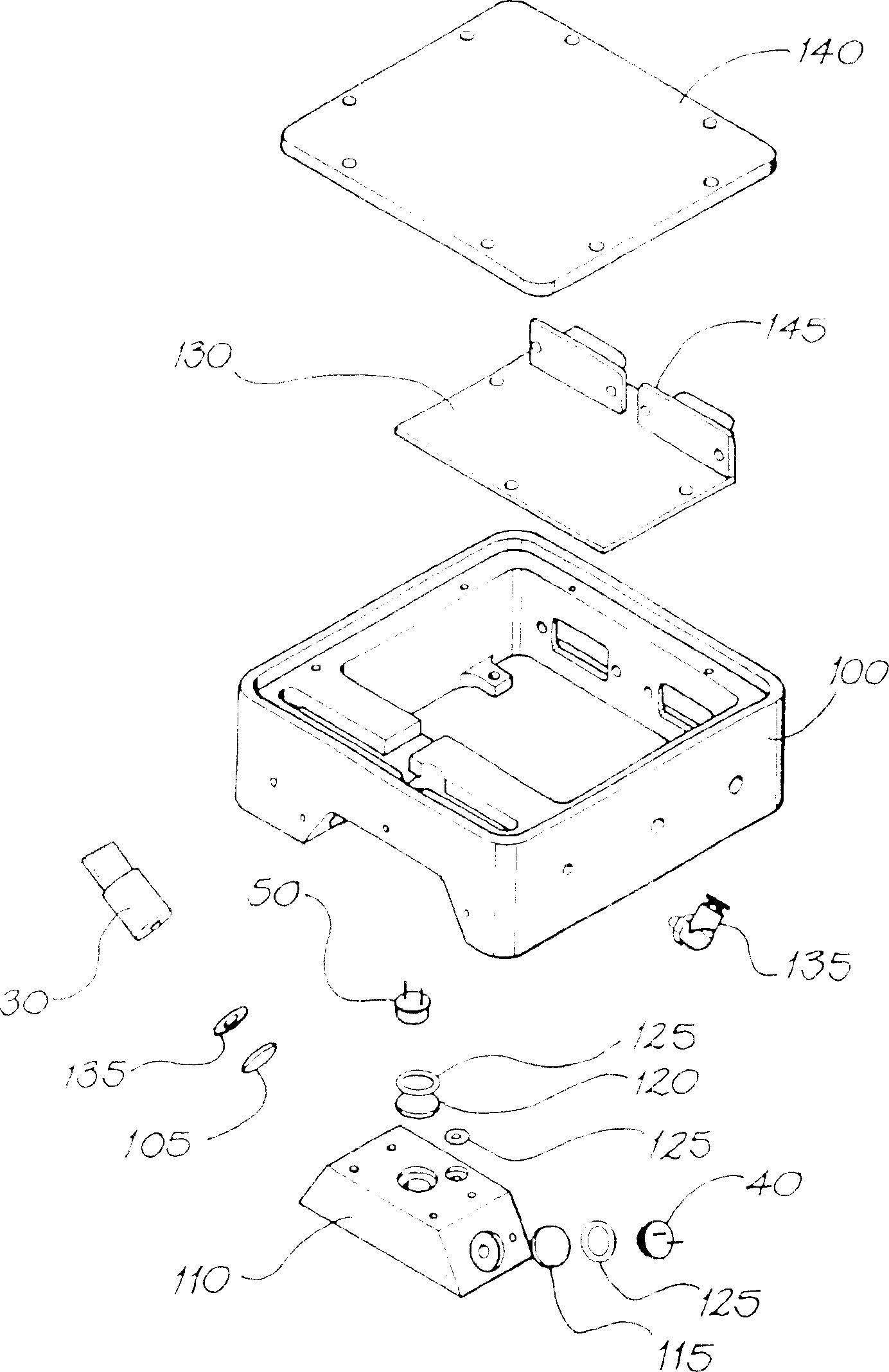
[0088] figure 1 An instrument 10 is shown in which a housing 20 containing electronic components (to be described hereinafter) contains a direct light source 30 , a reflected light detector 40 and a scattered light detector 50 . The light of the light source is incident according to the incident path 35 and interacts with the (ideal) film surface 58 on the printing plate 60 , causing reflections on the specular path 45 and the diffuse path 55 .

[0089] The direct light source 30 may be any light source, but is preferably a laser because of its availability and ease of obtaining a light source directed at a given target. Detectors 40 and 50 are readily implemented by commercially available silicon cell detectors. For clarity, the optical filters and detectors 40, 50 associated with the light source 30 are not shown.

[0090] More specifically, the light source 30 is typically a 650 nm, 3 mW diode laser module with a collimating lens 300-0360-78...


PUM


Abstract

The invention discloses a method for operating an offset printing machine, a control device thereof, an offset printing machine and offset printing materials. The method of operating an offset printing press comprises the steps of: (a) directing a beam of light onto an offset printing plate of an offset printing press comprising image areas bearing printing ink and non-image areas bearing fountain solution, the beam incident on the offset printing plate on, to scatter and specularly reflect from the flexographic printing plate, (b) detect the scattered light and provide a corresponding first signal representing the brightness of the detected scattered light and representing the amount of printing ink in the image area, whereby the first signal can be used In order to control the application of printing ink, (c) detect the specularly reflected light, and provide a corresponding second signal representing the intensity of the detected reflected light, (d) process the first signal to identify when the light falls on the image area, ( e) filtering the second signal using data obtained from processing the first signal to provide an output signal indicative of the amount of dampening solution present on the flexographic printing plate when light impinges on the non-image area.

Description

technical field [0001] This invention relates generally to films on moving or stationary surfaces, and more particularly to the near real-time monitoring of such films on printing plates of offset printing presses. Background technique [0002] Offset printing uses inks and dampening agents to differentiate the printing and non-printing areas of the printing plate. Hydrophilicity of non-image areas and lipophilicity of image areas are fundamental prerequisites for the offset printing process. Proper coverage of the image areas of the plate with ink and non-image areas of the plate with dampening agent is required to produce continuous high quality output. Clear and sharp images are produced when the ratio of ink to dampening agent is such that non-image and image areas can be clearly distinguished. [0003] Briefly, the non-printing areas have a layer of fountain, while the printing areas have a layer of photolithographic film with ink attached. There is also a small amou...

Claims


Application Information

Patent Timeline
Patent Type & Authority Patents(China)
IPC IPC(8): B41F33/00G01B11/06B41F33/14B41F31/02G01F23/28G01N21/47
CPCB41F33/0063G01B11/0625B41F33/00
Inventor 艾里斯戴尔·思考特·马丁罗杰·普莱斯·耐特菲尔得克里斯托弗·海叶斯·夫拉恩德曼蒂·格拉斯戴维·伊恩·弗拉恩特迈克尔·劳伦斯·布拉泽
Owner COMMONWEALTH SCI & IND RES ORG
Why Eureka
Try Eureka