Circuit for adjusting the drive power of emitting diodes

A technology of transmitting diodes and driving circuits, applied in the directions of repeaters/relay circuits, electrical components, electromagnetic wave transmission systems, etc., can solve the problems of increasing data volume and energy consumption, and achieve the reduction and reduction of data transmission energy. Transmission performance, effect of fast adjustment of drive current

Inactive Publication Date: 2006-07-12
ATMEL GERMANY +1
View PDF0 Cites 0 Cited by
  • Summary
  • Abstract
  • Description
  • Claims
  • Application Information

AI Technical Summary

Problems solved by technology

Energy consumption increases with increasing data volume in relation to transmission

Method used


Image

  • Circuit for adjusting the drive power of emitting diodes
  • Circuit for adjusting the drive power of emitting diodes
  • Circuit for adjusting the drive power of emitting diodes

Examples


example 1

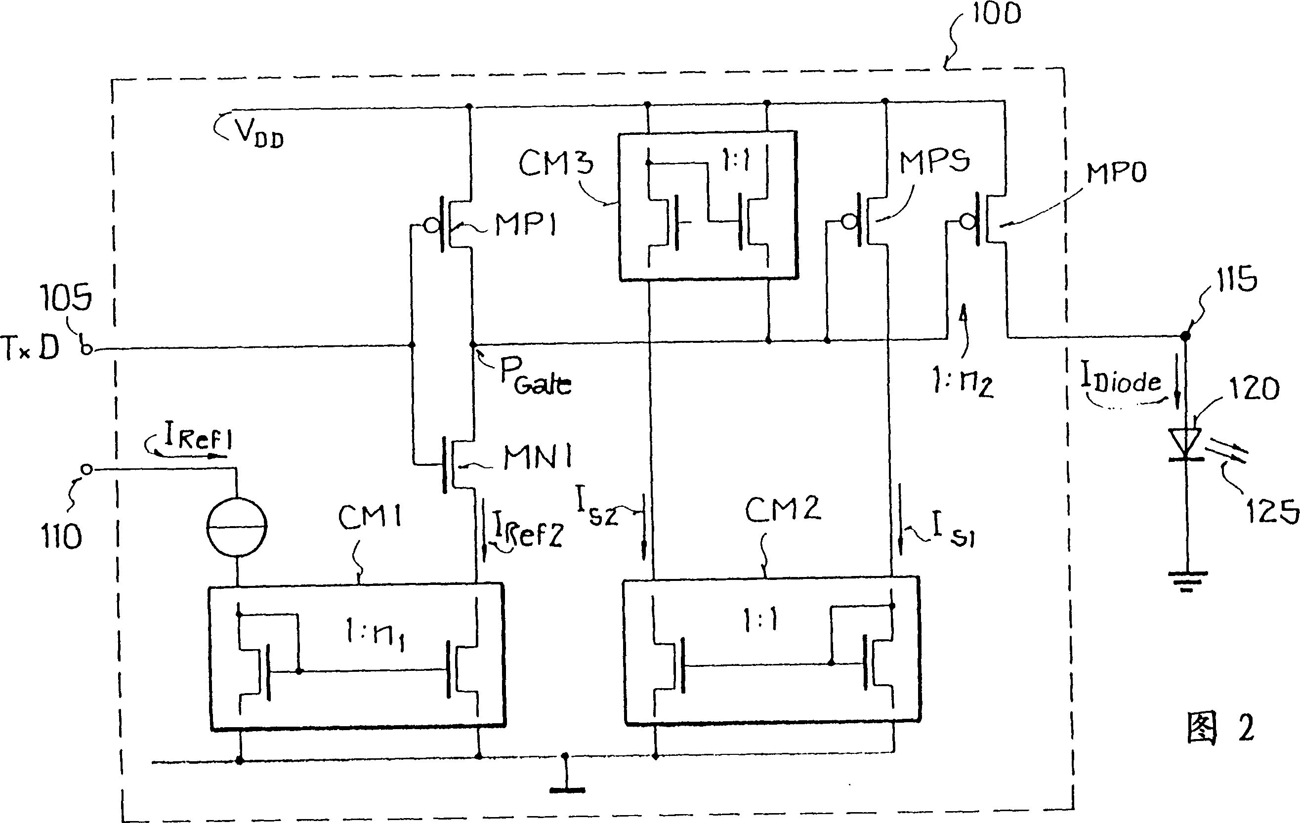
[0032] The first reference current I input to the second input terminal 110 of the driving circuit 100 Ref1 For example 12.5μA, this reference current will be amplified by the current mirror CM1 n 1 times, as illustrated in Figure 2 with the ratio "1:n 1 "Represented. When the input signal TxD of the first input terminal 105 of the input driver circuit 100 was in a low state (ie TxD=0), the NMOS transistor MN1 was turned off and the PMOS transistor MP1 was turned on. Therefore in this state The switching node PGate remains at the voltage V DD superior. If the input signal TxD for the transmit pulse transitions to a high state (TxD=1), the PMOS transistor MP1 is turned off and the NMOS transistor MN1 is turned on, wherein the reference current I amplified by the current mirror CM1 Ref2 Discharge the node PGate. This discharge causes the voltage of the switching node PGate to drop until the transistors MPO and MPS are turned on. Through the switching of the transistors MPS ...


PUM


Abstract

A method for setting the trigger power of transmitter diodes that transmit data via optical paths allows the transmission power to be adjusted and adapted to the communication distance. The trigger power is determined for the present communication distance on the basis of a test signal before data transmission begins. A circuit arrangement implementing the method includes a driver circuit with a switching device that switches a circuit junction point selectively to a supply voltage or to a constant reference voltage, a voltage-controlled resistor which delivers the driver current and is controlled from the circuit junction point, and a voltage-controlled measuring resistor which delivers a measured current with a fixed relationship to the driver current and is controlled from the circuit junction point. Since the set trigger power can be reduced, the power consumption for data transmission can be reduced considerably.

Description

technical field [0001] The invention relates to a circuit for adjusting driving power of an emitting diode transmitting data on an optical path. Background technique [0002] Data transmission over optical paths such as in the infrared wavelength range is best used over short distances, eg for communication from mobile phones and laptops to personal computers (PCs). Another application is data exchange between printers and PCs. The transmission is standardized and generally works in the system in the infrared region and is based on the so-called IrDa protocol (IrDa=Infrared Data Association). Since the data transmission takes place bidirectionally, a transmitting and receiving unit combining these parts is used, which consists of a so-called transceiver circuit for driving a transmitting-receiving diode. The transceiver circuit itself is composed of a receiving circuit, a transmitting circuit (also called a driving circuit) and an interface circuit, and the interface circu...

Claims


Application Information

Patent Timeline
Patent Type & Authority Patents(China)
IPC IPC(8): H04B10/10H04B10/152H04B10/11H04L25/26
CPCH04B10/11H04L25/26
Inventor 莱纳·罗登赫伯约翰·豪尔吉恩斯·伊格勒尔迈克尔·雷恩霍尔德
Owner ATMEL GERMANY
Why Eureka
Try Eureka