
Method for suppressing self-phase modulating effect in over long-distance optical transmission system

A technology of self-phase modulation and optical transmission, which is applied in transmission systems, electromagnetic wave transmission systems, optical fiber transmission, etc., can solve the problems that are not suitable for ultra-long-distance optical transmission systems, and achieve the effects of suppressing the SPM effect, improving performance, and operating reliably

Inactive Publication Date: 2006-07-26
HUAWEI TECH CO LTD
View PDF0 Cites 0 Cited by
  • Summary
  • Abstract
  • Description
  • Claims
  • Application Information

AI Technical Summary

Problems solved by technology

[0009] To sum up, the two existing methods of suppressing the SPM effect reduce the SPM effect at the expense of the transmission distance, which is not suitable for ultra-long-distance optical transmission systems

Method used


Image

  • Method for suppressing self-phase modulating effect in over long-distance optical transmission system
  • Method for suppressing self-phase modulating effect in over long-distance optical transmission system
  • Method for suppressing self-phase modulating effect in over long-distance optical transmission system

Examples


Embodiment Construction

[0020] The method of the present invention is further analyzed and illustrated below in conjunction with the accompanying drawings.

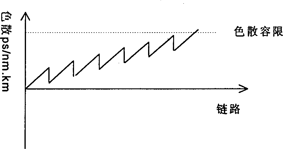
[0021] The present invention adopts the optimized dispersion compensation technology, and takes the SPM effect generating area (the optical power input end of the optical fiber) as the reference point to ensure that the cumulative dispersion from any reference point to the receiver is positive, so that the SPM effect generated by the reference point It interacts with dispersion to compress the stretched pulse and improve the performance of the system. This technology is applicable to any system that adopts dispersion compensation module for dispersion compensation.

[0022] like image 3 A point-to-point optical transmission system is shown. In the link, n optical fiber spans are used as a compensation unit, and there are m compensation units in total. Before the DCM (dispersion compensation module), there is an amplifier to compensate the po...


PUM


Abstract

Dispersion compensation module is utilized in each chain to carry out distributivity full compensation for dispersion. Position and dispersion quantity of dispersion compensation module in chain are adjusted. With input point of optical signal power as the reference point, accumulated dispersion quantity from any reference point to front of receiver is positive. Total dispersion of system is within dispersion tolerance of receiver. Interaction between effect of self phase modulation (SPM) and dispersion is created to compress expanded pulse. The method is suitable to DWDM system, possible to control the accumulated total residual dispersion. Thus, transmission distance is not limited by linear dispersion. Under current technical condition of dispersion compensation, without need of adding any new part, SPM effect in ultralong distance transmission can be solved in entire C-BAND. The method is reliable through emulation, simulation, experiments and applicable test.

Description

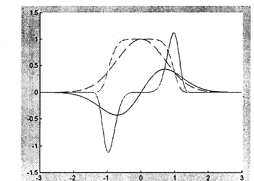
technical field [0001] The invention belongs to the technical field of ultra-long-distance optical transmission, in particular to a method for suppressing self-phase modulation (SPM) effect in an ultra-long-distance optical transmission system. Background technique [0002] In a high-speed, ultra-long-distance optical transmission system, a higher input fiber power is used to ensure the optical signal-to-noise ratio (OSNR) at the receiving end. Higher power leads to the generation of SPM effect, which makes the front and rear edges of the light pulse figure 1 Redshift and blueshift shown. The SPM effect is irreversible and will continue to accumulate along with the link, and the accumulated SPM effect will lead to degradation of system performance. Therefore, in high-speed ultra-long-distance optical transmission systems, effective methods must be used to suppress the SPM effect. [0003] The frequency distribution of the optical pulse is that the high-frequency component...

Claims


Application Information

Patent Timeline
Patent Type & Authority Patents(China)
IPC IPC(8): H04J14/02H04B10/08H04Q3/52G02B21/00H04B10/2513
Inventor 钟胜前柳贺良
Owner HUAWEI TECH CO LTD
Learn More