Electrolytic capacitor

A technology for electrolytic capacitors and capacitors, applied in the direction of electrolytic capacitors, capacitors, capacitor parts, etc., can solve the problem of not playing a restraining role, and achieve the effect of preventing reduction and prolonging the service life

Inactive Publication Date: 2000-12-20
RUBYCON CORPORATION
View PDF1 Cites 7 Cited by
  • Summary
  • Abstract
  • Description
  • Claims
  • Application Information

AI Technical Summary

Problems solved by technology

However, it did not play an inhibitory role, so it still nee

Method used


Image

  • Electrolytic capacitor
  • Electrolytic capacitor
  • Electrolytic capacitor

Examples


example 1

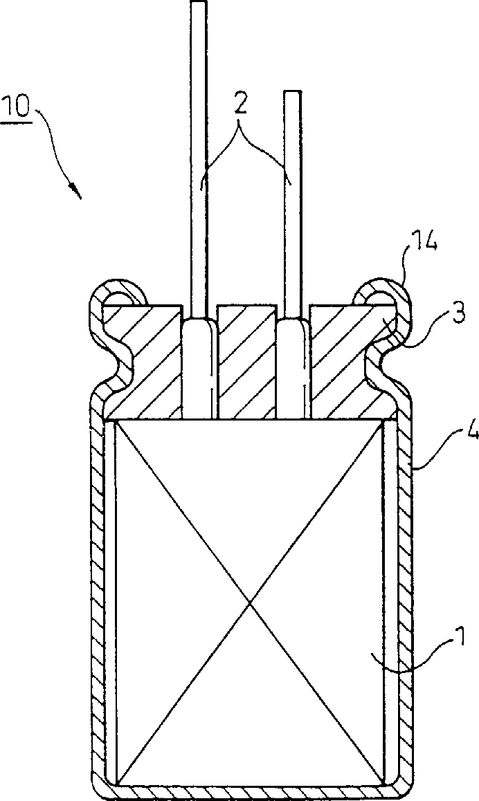
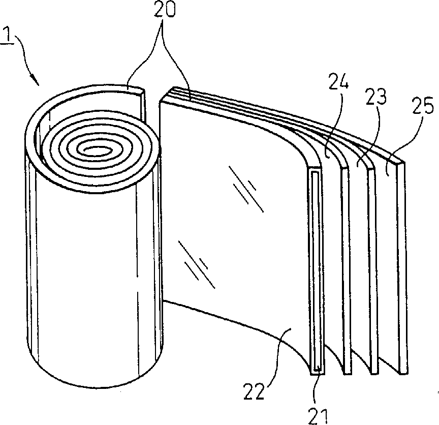
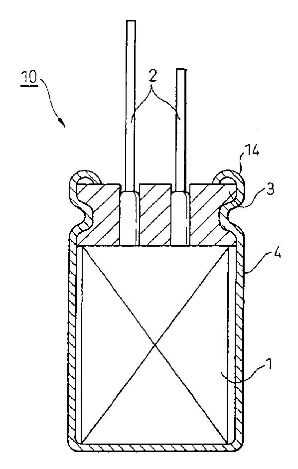
[0062] An aluminum electrolytic capacitor with a coiled structure was prepared according to the following steps.

[0063] First, the aluminum foil is electrochemically corroded, and then anodized to form an anodized film on the entire surface of the aluminum foil, and then connected to a wire joint that leads out the electrode to obtain an aluminum anode electrode. The other aluminum foil is also electrochemically etched, and a lead terminal of an extraction electrode is connected to the foil to form an aluminum cathode foil. Next, a capacitor element was prepared by inserting a separator between the anode electrode and the cathode electrode, followed by crimping. The release paper used here is a paper prepared by using Manila hemp as a raw material. Its cation content is as low as 489ppm due to the washing steps employed in the papermaking process. Then use the electrolytic solution described below to impregnate the capacitor element, and place it in a closed-end aluminum s...

example 2 and 3

[0070] In these two examples, except that the cation content in the release paper used was adjusted to 280ppm (example 2) or 120ppm (example 3), the same process as example 1 was repeated, and the results shown in Table 1 below were obtained. Comparative Examples 1 to 3


PUM


Abstract

An electrolytic capacitor comprises a capacitor element consisting of strips of metal foil separated by insulating paper, and liquid electrolyte. The insulating paper contains 500 ppm or less cation. The electrolytic capacitor has low impedance, preferred low-temperature characteristics and a long service life, and it is capable of operating at high temperature.

Description

technical field [0001] The present invention relates to an electrolytic capacitor. In particular, the present invention relates to an electrolytic capacitor characterized by low impedance, and excellent low-temperature stability and heat resistance, and good service life. Background technique [0002] A capacitor is a conventional electrical component and is widely used in various electrical and electronic products, and it is mainly used in a power supply line, a noise filter of a digital line, and the like. [0003] Various types of electrolytic capacitors are now well known. These include aluminum electrolytic capacitors, wet tantalum electrolytic capacitors, and more. Among these electrolytic capacitors, excellent performance can be expected by the aluminum electrolytic capacitor in practice of the present invention, and therefore, the present invention will be described in detail with reference to this electrolytic capacitor. As used herein, "electrolytic capacitor" m...

Claims


Application Information

Patent Timeline
IPC IPC(8): H01G9/02H01G9/022
CPCH01G9/02H01G9/022H01G9/035H01G9/10
Inventor 小松昭彦
Owner RUBYCON CORPORATION
Why Eureka
Try Eureka