
Domestic garbage continuous incinerator

A domestic garbage and incinerator technology, applied in the direction of incinerator, combustion method, combustion type, etc., to achieve the effect of ensuring combustion quality and low treatment cost

Inactive Publication Date: 2006-11-01
滕清华
View PDF0 Cites 0 Cited by
  • Summary
  • Abstract
  • Description
  • Claims
  • Application Information

AI Technical Summary

Problems solved by technology

At present, there is no practical kiln that can be completely and continuously burned without adding auxiliary fuel and sorting garbage, and is worthy of promotion.

Method used

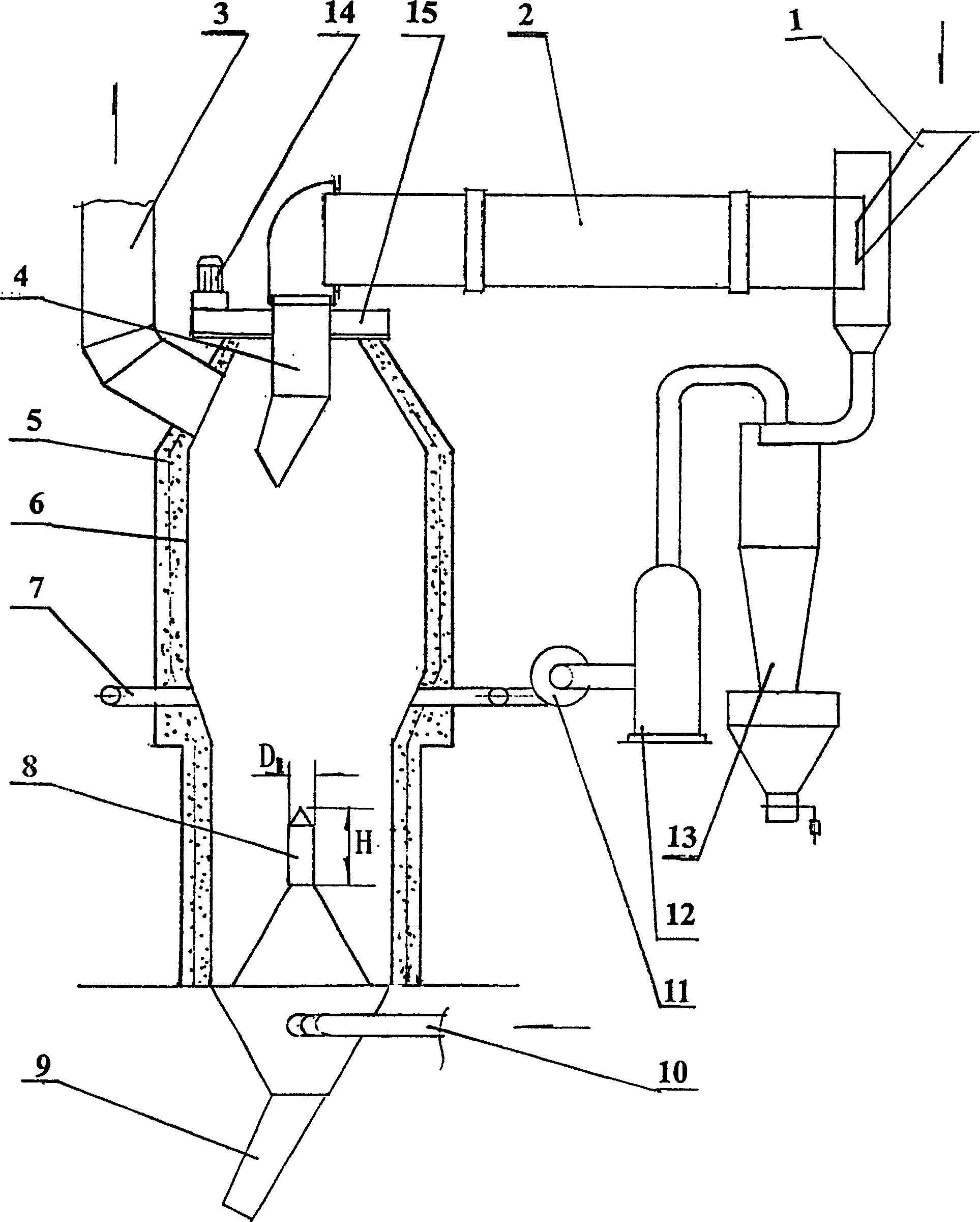
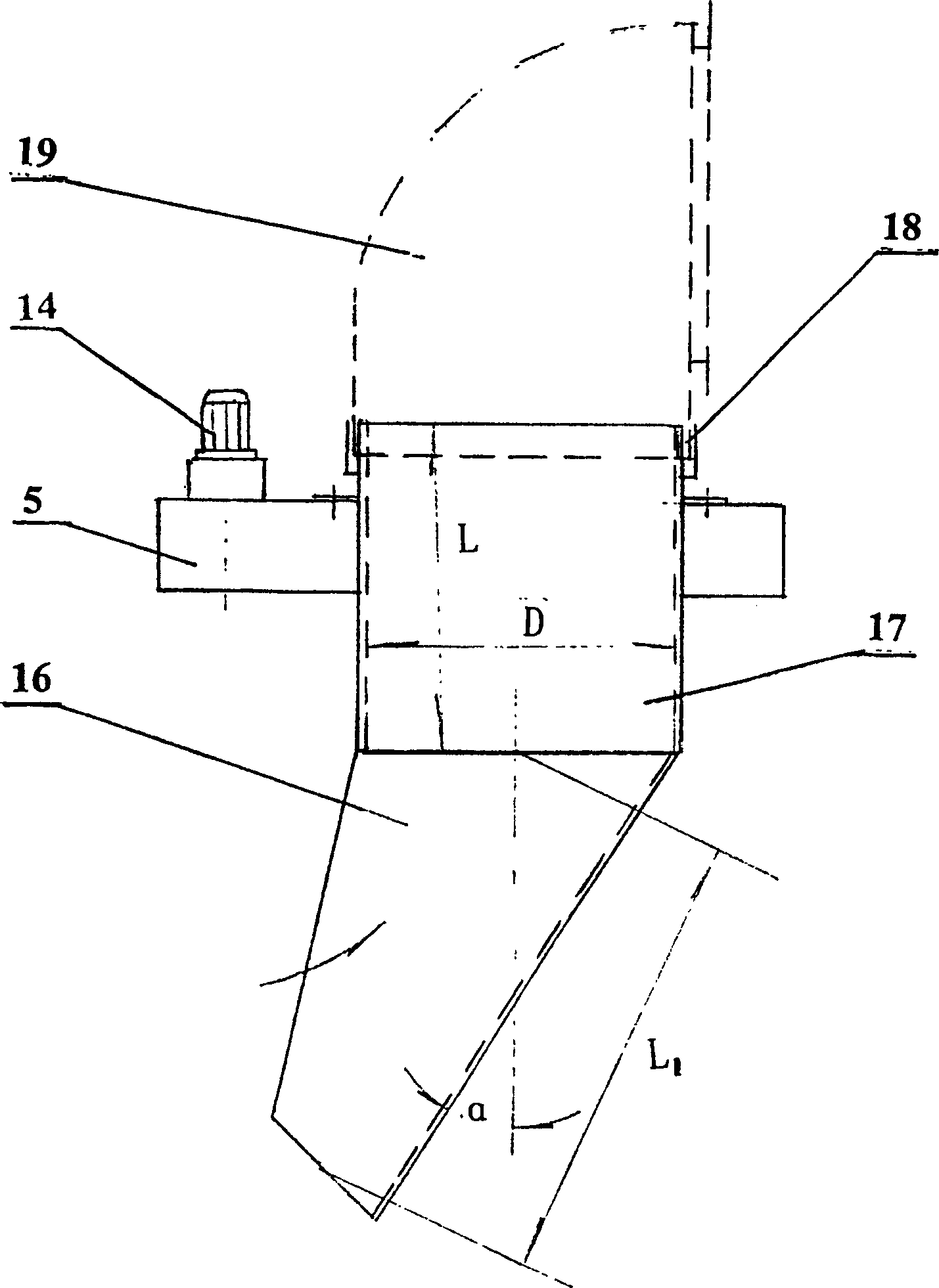
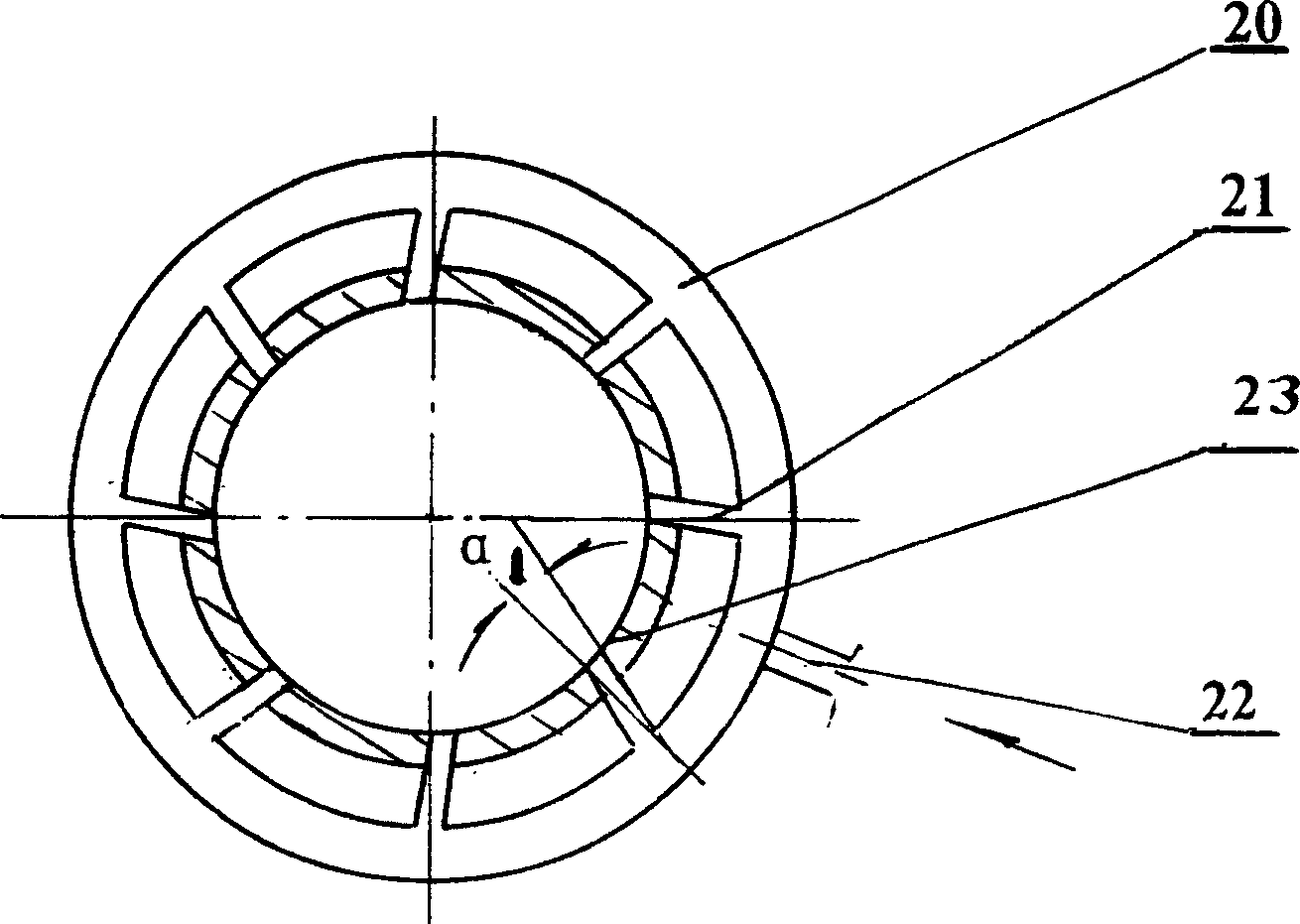

Image

  • Domestic garbage continuous incinerator
  • Domestic garbage continuous incinerator
  • Domestic garbage continuous incinerator

Examples


Embodiment Construction

[0015] As shown in each figure, it is a continuous incinerator for domestic waste. It includes a rotary drying and heating system 2, a rotary material distribution system 4, a furnace body 5, an air induction system, a high temperature resistant fan 11, an oxygen enrichment device 12 and a water vapor separator 13. The upper part of the furnace body 5 is provided with a chimney 3 , and the lower part is provided with a slag outlet pipe 9 and an air inlet pipe 10 . The rotary drying and burning system 2 is set on the top of the furnace body 5, one end of which is equipped with a feed hopper 1, and this end also passes through the water vapor separator 13, the oxygen enrichment device 12, the high temperature resistant fan 11 and the annular air inlet pipe device in sequence 7 connected to each other. The rotary distribution system 4 is installed on the top of the furnace body 5, the middle part is a distribution pipe 17, the top of the distribution pipe is connected with a sea...


PUM


Abstract

The present invention relates to a domestic refuse continuous incinerator. It includes the components of rotary drying and combustion system, chimney, rotary distributor system, furnace body, non-sticky furnace wall, air-inducing and air-feeding system, air inlet tube, slag discharge pipe, high-temp. fan, oxygen-enriching device, water-vapour separator and feeding hopper, etc.

Description

Technical field [0001] The invention relates to an environmental protection device, in particular to a continuous domestic waste incinerator. Background technique [0002] In real life, a large amount of domestic waste is produced, which will cause great pollution if not treated. At present, the disposal of domestic waste, especially urban domestic waste, has attracted the attention of various countries. The landfill method is rarely used. Most of them are incinerated in furnaces and kilns. Most foreign furnaces are fueled with auxiliary fuels such as fuel or coal. Although the treatment effect is better, the operating cost is high. Some domestic stoves add fuel to support combustion, and some need to sort garbage before burning. Also do not see at present do not add auxiliary fuel, do not just can complete continuous burning and the practical kiln that is worth popularizing without sorting rubbish. Contents of the invention [0003] The object of the present inventio...

Claims


Application Information

Patent Timeline
Patent Type & Authority Patents(China)
IPC IPC(8): F23G5/04F23G5/46F23G5/44
CPCY02E20/34
Inventor 滕清华
Owner 滕清华
Learn More