Fine pitch anisotropic conductive adhesive

A conductive adhesive, anisotropic technology, applied in the direction of conductive adhesives, film/sheet adhesives, adhesives, etc., can solve problems affecting the reliability of electrical connections

Inactive Publication Date: 2001-08-08
3M CO
View PDF12 Cites 40 Cited by
  • Summary
  • Abstract
  • Description
  • Claims
  • Application Information

AI Technical Summary

Problems solved by technology

[0015] In addition to these size factors, restrictions on the types of particles that can

Method used


Image

  • Fine pitch anisotropic conductive adhesive
  • Fine pitch anisotropic conductive adhesive
  • Fine pitch anisotropic conductive adhesive

Examples


Embodiment Construction

[0067] The following examples describe various specific embodiments of the invention and these examples should not be construed as limiting the scope of the invention or the appended claims.

[0068] FIGS. 6( a ) to ( e ) are each micrographs taken of the dimpled tool of the present invention after filling the dimples of the tool with conductive particles according to the method of the present invention. Each photomicrograph shows a tool with pits (pockets filled with conductive particles) arranged in a periodic rectangular array. The size of the dimples, the size of the dimple array, and the type of particles vary. In each case, the depth of the depressions is such that the particles exist as a single layer in the depressions. Different dimple patterns, particle types and particle size distributions provide different particle counts per particle site per pattern. In all cases, however, no particles were seen remaining on the tool area between the dimples.

[0069]Figure 6(...


PUM


Abstract

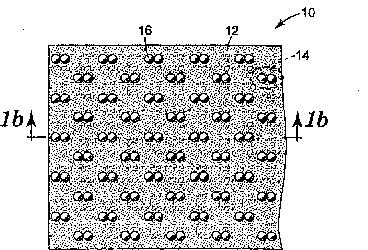
Disclosed is an anisotropic conductive adhesive (10) having an adhesive layer (12) and conductive particles (16) individually adhered to the adhesive layer, the conductive particles being arranged in an ordered array. The size of the conductive particles is at least somewhat smaller than the thickness of the adhesive layer. Also disclosed is an anisotropic conductive adhesive having an adhesive layer, conductive particles individually adhered to the adhesive layer, and a release liner (28) having an ordered array of dimples. The conductive particles reside in a single layer in the dimples. The anisotropic conductive adhesive is made by placing the conductive particles in an ordered array of dimples on a low adhesion surface. An adhesive layer is then laminated on top such that the conductive particles individually adhere to the adhesive layer. The anisotropic conductive adhesive may be used to electrically connect fine pitch electrodes on opposing circuit layers.

Description

field of invention [0001] The invention relates to an anisotropic conductive adhesive and a preparation method thereof. Background of the invention [0002] Conductive adhesives generally provide a convenient and useful means of achieving adhesion and electrical connection between pad electrodes on two separate circuits or layers of a multilayer circuit. Anisotropic conductive adhesives (also known as z-axis conductive adhesives) can be used when many individual patch electrodes are each within a small area. The anisotropic conductive adhesive conducts electricity between opposing electrodes through the adhesive, but does not conduct electricity in the plane direction of the adhesive. In this way, adjacent pad electrodes, which are intended to be independently conductive, remain electrically separated from each other while they are bonded and electrically connected to mating electrodes on opposing circuits or circuit layers. [0003] One metho...

Claims


Application Information

Patent Timeline
IPC IPC(8): C09J7/00C09J9/02H05K3/32
CPCH05K3/323H05K2201/10234H05K2201/09945H05K2203/0338C09J9/02H05K2203/0113Y10T156/109Y10T156/1093Y10T428/14Y10T428/24372Y10T428/24413Y10T428/24669Y10T428/24678C09J5/06C09J2203/326
Inventor G·康萘尔B·S·卡彭特P·B·霍格通山口裕显
Owner 3M CO
Why Eureka
Try Eureka