Measuring method and instrument comprising image sensor
A technology of an image sensor and a measurement method, which is applied to the device implementing these methods, and the measurement field of the measured substance of the sample concentration, which can solve the problems of uneven light and poor sensitivity, etc.
- Summary
- Abstract
- Description
- Claims
- Application Information
AI Technical Summary
Problems solved by technology
Method used
Image


Examples
Embodiment 1
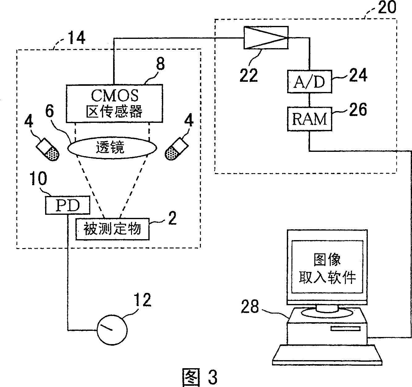
[0085] As Example 1, an area sensor is used as a sensor, and a two-dimensional reflectance measurement device to which the output correction method based on the first aspect of the present invention is applied is shown.
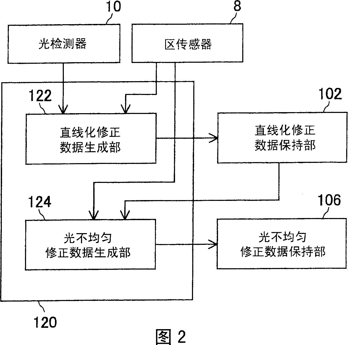
[0086] The linearization correction data held in the linearization correction data storage unit 102 and the optical unevenness correction data held in the optical unevenness correction data storage unit 106 can be generated in the reflectance measurement device or the test piece measurement device. Therefore, as shown in FIG. 2 , it is desirable to further have: a photodetector 10 that is installed at a position to receive reflected light from a test piece held on a sample stage, and has a linear output for the amount of light received; The output of the image sensor when the amount of light changes is proportional to the output of the photodetector 10, and the linearization correction data of the output of the image sensor 8 is corrected, and stored in the li...
Embodiment 2
[0191] As a second embodiment of the reflectance measuring device, FIG. 16 shows the outline of a device to which the second correction method is applied.
[0192] Compared with the reflectance measurement device of FIG. 3 , the difference is that the photodetector 10 for monitoring the light quantity is not arranged. Other structures are basically the same. The reflected light of the object 2 passes through the reflector 5, passes through the lens 6, and forms an image on the area sensor 8a. Zone sensor 8a is shown to include amplifier 22 of FIG. 3 . The detection signal of the area sensor 8a passes through the A / D converter 24, and is read by the calculation part 28a. Calculator 28a corresponds to RAM 26 and personal computer 28 in FIG. 3 . A display 30, a keyboard 32, and a printer 34 are connected to the calculation unit 28a. 36 is an image storage unit for storing read image data, and is constituted by, for example, a hard disk device. In order to convert the reflecta...
Embodiment 3
[0205] As a third embodiment of the reflectance measuring device, a device to which the output correction method according to the third aspect is applied will be described.
[0206] The optical system is the same as that shown in Figure 16.
[0207] In this embodiment, an area sensor 8a whose exposure time to light is programmable is used. As such an area sensor, for example, a CMOS image sensor (H64283FP) manufactured by Mitsubishi Corporation used in the embodiment of FIG. 3 is used. However, the area sensor 8a used is not limited to a CMOS image sensor, that is, a CCD image sensor can be used as long as its exposure time is programmable.
[0208] Although the output of the area sensor 8a does not have linearity with respect to the amount of received light, the amount of received light is proportional to the exposure time. In addition, since the amount of light received is proportional to the reflectance, by using one reference plate and making the exposure time different,...
PUM
 Abstract
Description
Claims
Application Information
 - R&D
- Intellectual Property
- Life Sciences
- Materials
- Tech Scout
- Unparalleled Data Quality
- Higher Quality Content
- 60% Fewer Hallucinations
Browse by: Latest US Patents, China's latest patents, Technical Efficacy Thesaurus, Application Domain, Technology Topic, Popular Technical Reports.
© 2025 PatSnap. All rights reserved.Legal|Privacy policy|Modern Slavery Act Transparency Statement|Sitemap|About US| Contact US: help@patsnap.com