Axially sliding connection brush appliance, its mfg. method and dynamo set with same brush

一种电刷装置、轴向滑动的技术,应用在机电装置、连接、控制机械能等方向,能够解决电刷减振器构件尺寸大、电刷弹性体恶化接触压力、不能减振器安装等问题,达到滑动连接位置状况好、优良减振效果、好接触稳定性的效果

Inactive Publication Date: 2007-04-18
TOKYO PARTS IND CO LTD
View PDF2 Cites 0 Cited by
  • Summary
  • Abstract
  • Description
  • Claims
  • Application Information

AI Technical Summary

Problems solved by technology

[0004] However, in the flat vibration motor with the above structure, the vibration generated by the rotation of the rotor is transmitted to the brush at the same time, making the contact state between it and the commutator unstable, and sparks are generated at the contact point, thereby The generation of harmful substances that cause electrical disturbances on the contact portion, or the reduction of the contact pressure that deteriorates the brush elastic body itself, significantly reduces the performance of the motor, and in the worst case does not cause starting.
[0005] Heretofore, the absorption of the vibration transmitted to the brush is to utilize the method of sticking the damper member on the brush arm portion of the brush. However, in the Kodaira type vibration motor having the above structure, due to The shape is extremely small, so there is no space to paste the shock absorber components, which will make the work too complicated
In particular, the size of the brush damper component corresponding to the violent vibration of the vibration motor is large, so there is a problem that it must be manufactured with high precision, and the damper cannot be easily attached to the brush.

Method used


Image

  • Axially sliding connection brush appliance, its mfg. method and dynamo set with same brush
  • Axially sliding connection brush appliance, its mfg. method and dynamo set with same brush
  • Axially sliding connection brush appliance, its mfg. method and dynamo set with same brush

Examples


Embodiment Construction

[0028] Hereinafter, embodiments of the present invention will be described with reference to the drawings.

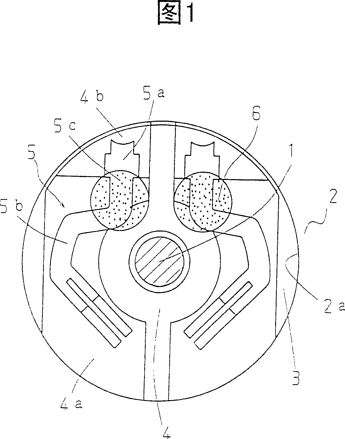
[0029] Fig. 1 is a top view of main parts showing a brush unit according to an embodiment of the present invention. In Fig. 1, the above-mentioned rotating shaft 1 is inserted through the central hole 2a of the annular stator magnet 2 fastened coaxially with the rotating shaft 1 of the motor. In the gap between the brackets 3, a brush base 4 is installed insertedly, which is fastened on one side of the bracket 3. On the exposed portion 4b of the stencil portion 4a of the brush base 4, the fastening portion 5a of the brush 5 is fastened by a method (soldering, welding, etc.) that does not affect conduction.

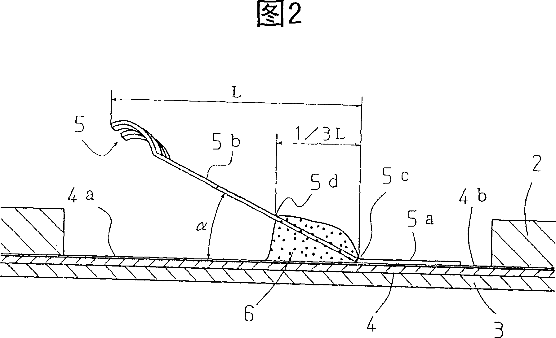
[0030] On the other hand, a pair of brush arms 5b are arranged symmetrically to the center of the rotating shaft 1, and the brush arms 5b have a planar curved shape in order to further increase the spring effective length of the brush arms 5b in a narrow space. Fu...


PUM


Abstract

The object of this invention is to prevent damage to the vibration damping property of a brush even for a violent vibration, and to enable frequently a stale contact between the brush and a commutator. The brush (5) is disposed at an elevation angle less than 45 degrees relative to a brush base (4) fixed to a bracket (3) such that the free end thereof is connected slidably to a flat commutator. The flat portion (5a) of the base portion of the brush is fixed to the exposed portion (4b) of the pattern (4a) of the brush base 4 by soldering. The base portion of the brush is coated with ultraviolet curable acrylic-based resin (6) to cover, at a maximum, about 1 / 3 of the projection length of the side face from the base portion to the brush arm portion of the brush.

Description

technical field [0001] The present invention relates to an improvement of an axial sliding connection type brush device of a flat motor used in a calling mechanism of a mobile communication device and the like; more particularly, the present invention relates to enabling the above-mentioned The vibration-damping properties of the flat vibration motor brushes are improved, and the contact between them and the commutator can be stabilized. Background technique [0002] In recent years, mobile communication technology has been increasingly developed, and efforts to reduce the weight and thickness of mobile communication devices are being accelerated. Correspondingly, as the vibration motor of the calling mechanism, a small flat type vibration motor is mostly used. [0003] Generally, the structure of the above-mentioned small flat vibration motor is centered on the rotating shaft, and a flat rotor fastened to a flat commutator, a flat stator magnet, an axial sliding connection...

Claims


Application Information

Patent Timeline
Patent Type & Authority Patents(China)
IPC IPC(8): H02K5/14H02K7/075H02K13/00H01R39/06H01R39/24H01R39/46H02K7/06H02K7/065H02K15/02H02K23/00H02K33/00
CPCH02K13/006H01R39/24H02K7/061H01R39/06H01R39/46H02K5/14H02K33/00
Inventor 小林元八岛哲志苏原胜仁
Owner TOKYO PARTS IND CO LTD
Why Eureka
Try Eureka