
Common rail for diesel engine

A diesel engine and common rail technology, applied in the field of common rail, can solve the problems of poor strength, failure to function, and deterioration of internal pressure fatigue strength, and achieve the effect of good durability and improved fatigue strength

Inactive Publication Date: 2007-05-16
USUI KOKUSAI SANGYO KAISHA LTD
View PDF10 Cites 2 Cited by
  • Summary
  • Abstract
  • Description
  • Claims
  • Application Information

AI Technical Summary

Problems solved by technology

[0007] More specifically, for the common rail with improved fatigue strength against internal pressure described in (1), in which stress concentration generated on the inner periphery of the lower end of the side hole is relieved by forming a flattened portion, the The flattened portion is formed by extrusion on the inner peripheral surface of the main pipe facing the side hole, and for a common rail with increased fatigue strength against internal pressure described in (2), in which the side hole is made to pass through There is a residual compressive stress at and around the end of the main flow passage to counteract the tensile stress generated on the inner periphery of the lower end of the side hole. This countermeasure works on the above-mentioned flattened surface or a part of the residual stress, however, in Parts other than the above-mentioned parts, that is, on the flow path of the main pipe or the flow path of the side hole, cannot play a sufficient role
In addition, for (3) and (4), in which the branch pipe is made to protrude into the inside of the flow channel beyond the inner peripheral wall surface of the main pipe rail, the stress concentration on the corner of the flow channel in the side hole is resolved, however, for the inner The degradation of the fatigue strength of the pressure is inevitable. This is due to the implementation of the technical solutions (3) and (4), brazing is necessary, and the parts affected by such heat will inevitably deteriorate the strength.

Method used


Image

  • Common rail for diesel engine
  • Common rail for diesel engine
  • Common rail for diesel engine

Examples


Embodiment Construction

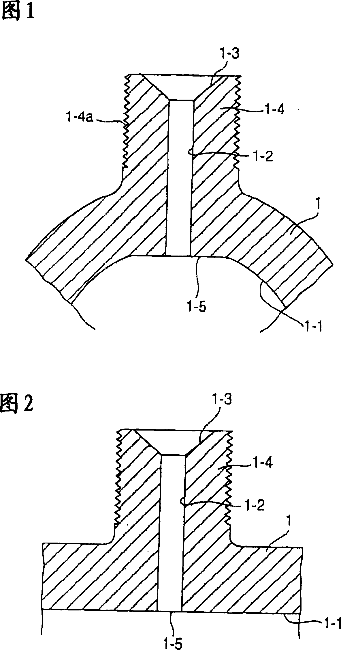
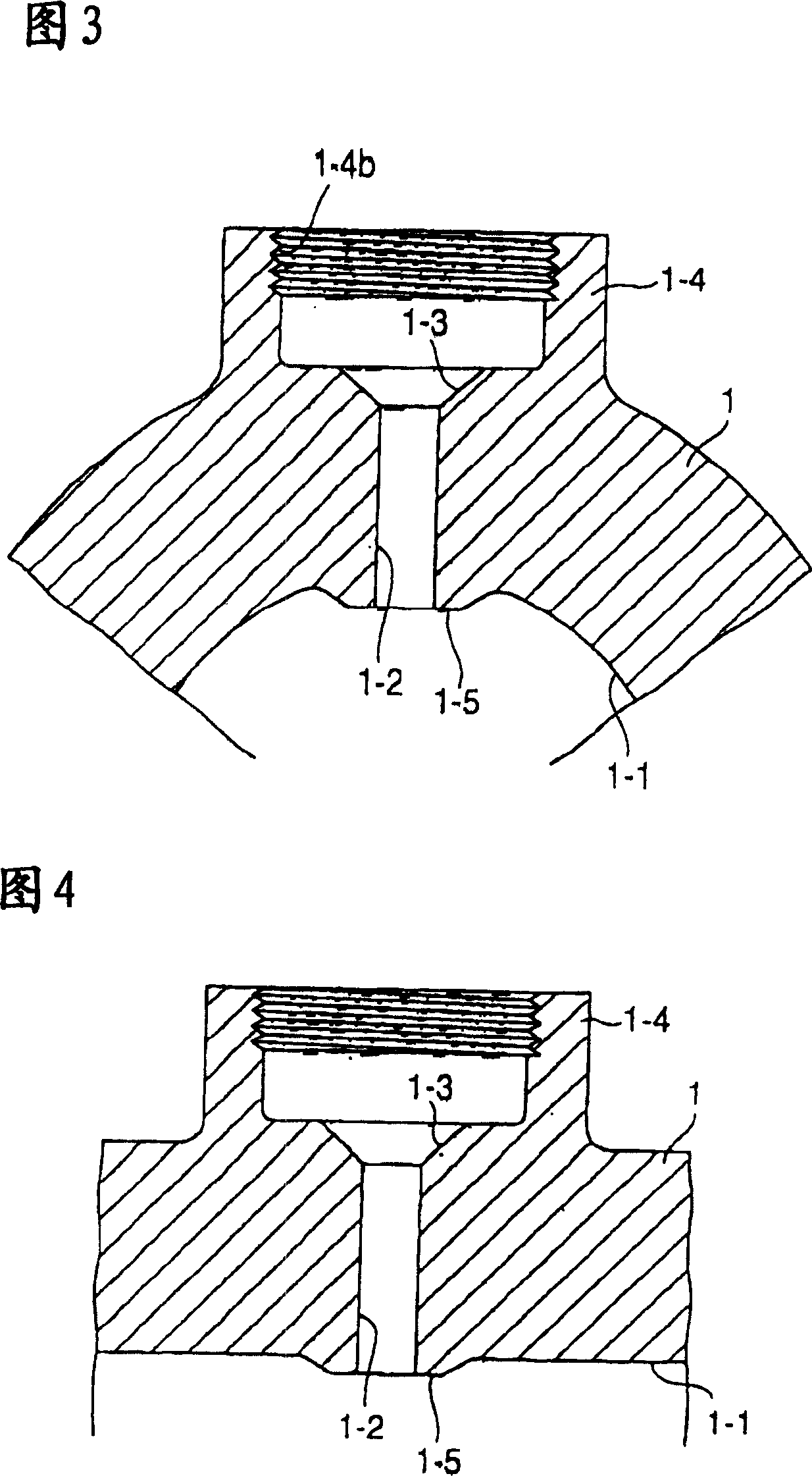
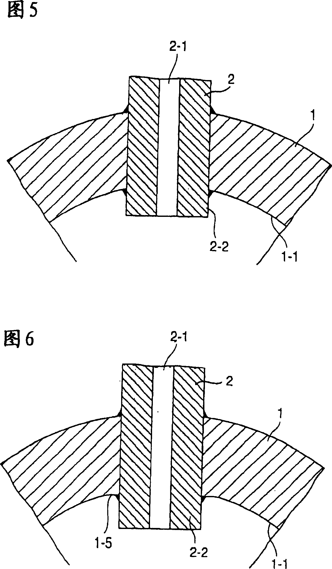
[0029] In the present invention, reference numeral 1 represents the main rail, reference numeral 1-1 represents the flow channel, reference numeral 1-2 represents the side hole, reference numeral 1-3 represents the surface of the pressure seat, and reference numeral 1- 4 represents a boss portion, reference numeral 1-4a represents a male thread, reference numeral 1-5 represents a flattened surface, reference numeral 2 represents a branch pipe, reference numeral 2-1 represents a flow channel, and reference numeral 2-2 Indicates a raised portion.

[0030]The main pipe rail 1 shown in Figures 1-4 as a common rail is a forging of S45C or similar material, having a tubular portion with a relatively thick wall, for example, a diameter of 28 mm and a wall thickness of 9 mm. The inside of the central axis is machined such as boring, deep hole drilling, etc. to form a flow channel 1-1, and a plurality of bosses are arranged on the peripheral wall, and are axially spaced apart from each...


PUM

PropertyMeasurementUnit
tensile strengthaaaaaaaaaa
yield pointaaaaaaaaaa

Abstract

A common rail, in which a flow passage in a main pipe rail and portions of branch holes are improved in durability while the portions of branch holes are enhanced in fatigue strength for inner pressures, is provided. A common rail for diesel engines, comprising branch holes made in a main pipe rail having therein a flow passage in an axial direction, to be communicated to the flow passage, wherein stress concentration in the vicinity of the branch holes is relaxed, and then a whole inner peripheral surface of the main pipe rail and the branch holes are subjected to autofrettage processing.

Description

technical field [0001] The present invention relates to a common rail in a fuel injection system of a diesel engine, such as a high-pressure fuel manifold, a block rail, etc., and more particularly to a common rail for a diesel engine, wherein one side on the main rail The fatigue strength of the hole or parts of the holes and the entire inner circumference of the main tube rail against internal pressure is increased. Background technique [0002] As everyone knows, the common rail in the fuel injection system of a diesel engine is a kind of structure, and in this structure, for example, as shown in Figure 7, a side hole 11-2 is arranged on the peripheral wall of the main pipe 11 that the circular tube constitutes, and The internal flow channel 11-1 communicates, and the side hole leads to an outwardly open pressure seat surface 11-3, and a cylindrical sleeve joint 13 is installed on the main pipe 11 by welding or brazing near the pressure seat surface. On the peripheral wa...

Claims


Application Information

Patent Timeline
Patent Type & Authority Patents(China)
IPC IPC(8): F02M55/02F02M55/00
CPCY10T29/49291F02M55/005F02M55/025F02M55/02
Inventor 臼井正佳
Owner USUI KOKUSAI SANGYO KAISHA LTD
Learn More