Method and apparatus for dialysate preparation and supply

A technology of hemodialysis and dialysate, applied in the field of hemodialysis medical treatment, can solve the problems of taking a long time to achieve, affecting the treatment effect, complicated shutdown operation, etc., saving time, simplifying the control principle, and low direct production cost. Effect

Active Publication Date: 2007-07-25
JINAN UNIVERSITY
View PDF10 Cites 2 Cited by
  • Summary
  • Abstract
  • Description
  • Claims
  • Application Information

AI Technical Summary

Problems solved by technology

Among the above two patents, the German patent solves the problem of liquid supply balance in the dialysate circuit, but the liquid dosing needs to be realized by setting up another liquid dosing device, and it is necessary to adopt the method of synchronous liquid dosing during the liquid supply, which is based on the flow rate and flow rate. The method of dosing liquid often appears in the dialysate circuit (balance chamber), and the attenuation of any electronically controlled valve body will cause the change of flow rate and the instability of conductivity, which directly affects the treatment effect; the Japanese patent solves the problem of dosing liquid problem, and the balance of the dialysate supply can only be achieved by using another balance device. The conductivity of this liquid distribution device is relatively stable, but due to space constraints, not only increases the hardware equipment, but also needs to be synchronized with the balance device Therefore, the flow rate (flow per unit time) of the dialysate flowing through the dialyzer on the dialysate circuit is difficult to be adjusted at will
The principles of the aforementioned two patents are realized on the basis that the liquid dosing and balanced liquid supply of the dialysate circuit are completed by two devices, which leads to the mixing of reverse osmosis water and concentrated A and B dialysates during the dialysate dosing process The ratio, reverse osmosis water flow rate (dialysate flow rate), and conductivity concentration must be set in advance, and cannot be changed arbitrarily during treatment. To adjust these parameters, you must stop the machine before resetting it. It will take a long time to achieve the desired value after restarting the machine. conductivity concentration, and the shutdown operation during the dialysis process is very complicated, which may cause major medical accidents. Therefore, all existing hemodialysis equipment does not have the function of stopping and changing parameters midway, and currently with the development of hemodialysis treatment technology, The number of treatment items based on the principle of hemodialysis has increased. The flow rate of the dialysate, which is internationally recognized as 500ml / min, can no longer meet the requirements of clinical treatment, and the existing technology cannot realize the clinical dialysis process according to the patient's condition (such as blood pressure, blood pressure, etc.) Pulse) to adjust the dialysate concentration online, so clinical treatment hopes to provide hemodialysis equipment that can adjust the dialysate flow rate and conductivity concentration during the dialysis process, while the existing liquid dosing and balanced supply in the dialysate circuit are respectively The method and device implemented by two devices are difficult to meet the requirements in this respect

Method used


Image

  • Method and apparatus for dialysate preparation and supply
  • Method and apparatus for dialysate preparation and supply
  • Method and apparatus for dialysate preparation and supply

Examples


Embodiment 1

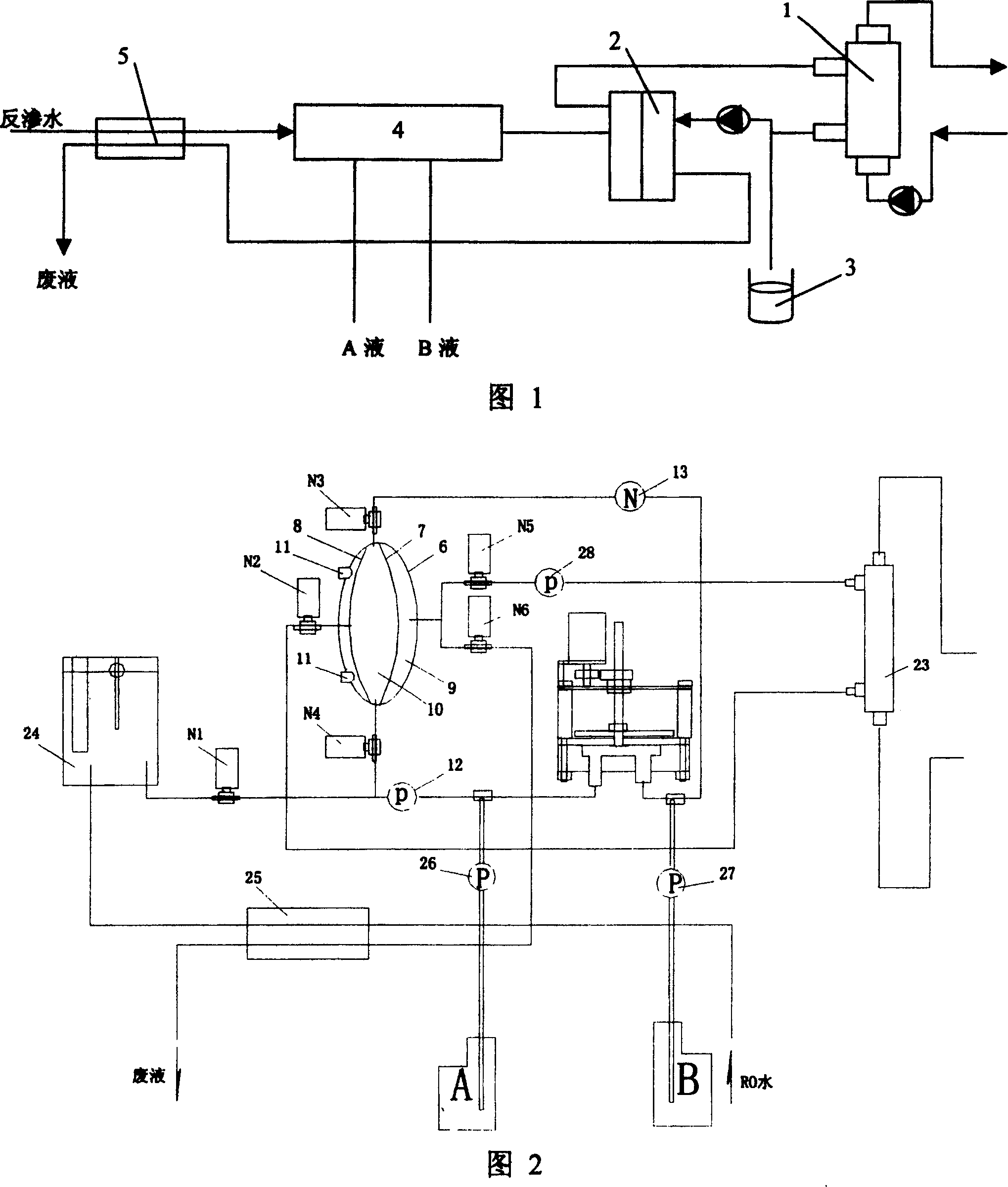
[0027] Fig. 2 has shown the specific structural form of the present invention, as can be seen from Fig. 2, this dispensing liquid supply device comprises an independent cavity 6, and the inside of this cavity is divided into two chambers 9, 10 by thin films 7, 8, wherein A film 8 is close to the cavity wall of the independent cavity 6, and a telescopic screw plug 11 that can fine-tune the space volume in the cavity from the outside is installed on the cavity wall; a chamber 10 between the two films 7, 8 is provided with a liquid Inlet and liquid dispensing outlet; electromagnetic valves N3 and N4 are provided on the pipes connected to the liquid dispensing outlet and the liquid distributing inlet, and the chamber 10 is also provided with an infusion outlet, and an electromagnetic valve N2 is provided on the pipe connected to the infusion outlet. The liquid inlet and the liquid distribution outlet are connected with the liquid delivery pump 12, the concentration fine-tuning devi...

Embodiment 2

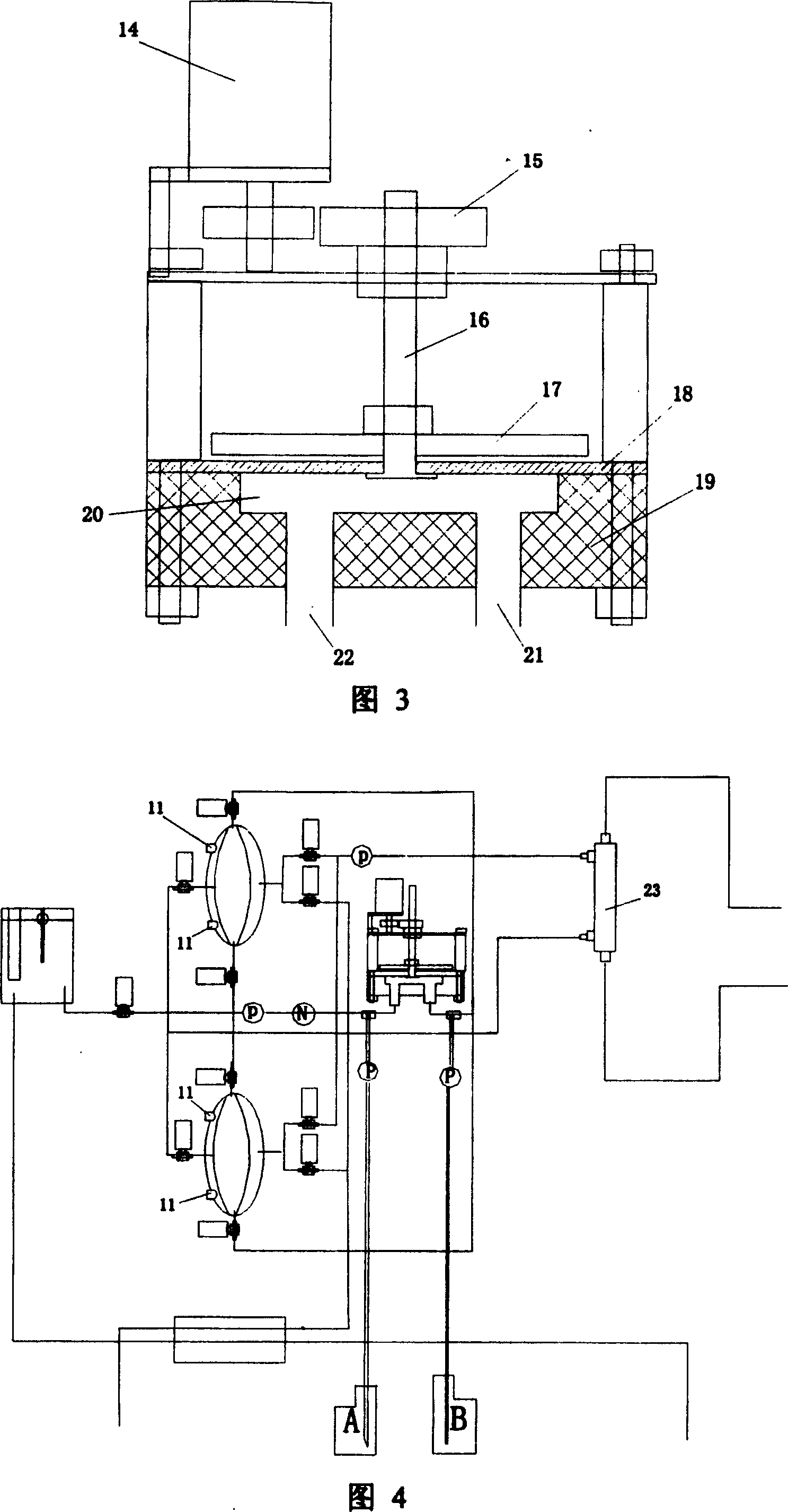
[0034] This embodiment is the same as Embodiment 1 except for the following features: two identical cavities are connected together for use, the specific connection method is shown in Figure 4, and two identical independent cavities are connected together. In this way, using two cavities with the same structure, when one cavity is dosing liquid, the other cavity will supply liquid in balance. For liquid supply, the two chambers are used alternately to realize uninterrupted balanced liquid supply to the dialyzer 23 . Since the two cavities use the same dosing control, the volumes in the two cavities must be consistent, otherwise the conductivity of the standard dialysate will deviate; for this reason, use the telescopic screw plug 11 on the cavity wall to adjust the volume of the cavity Change to make the volume of the two cavities consistent.

Embodiment 3

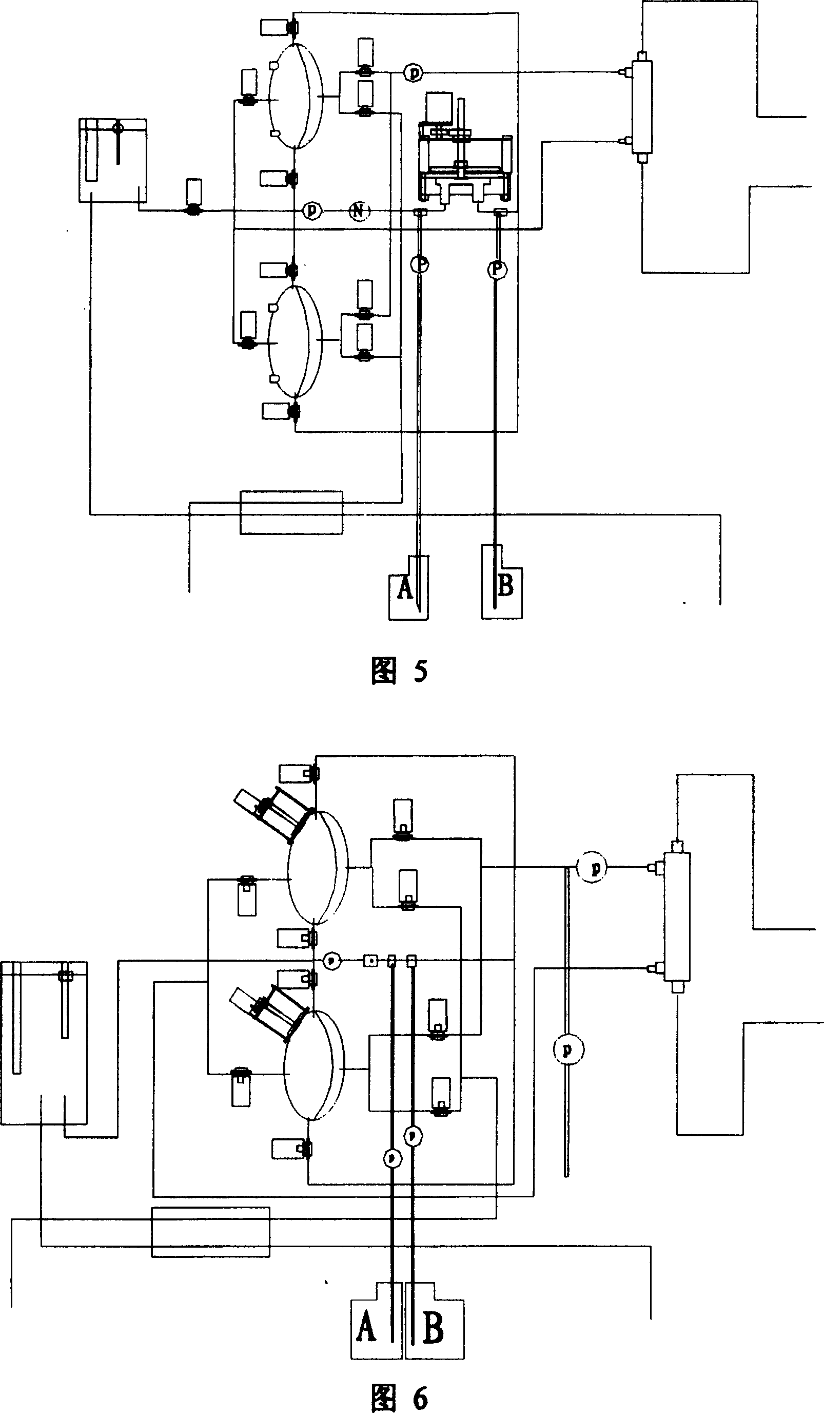
[0036] This embodiment is the same as Embodiment 2 except the following features: as shown in Figure 5, only a slice of film is set in the two cavities; this structure requires that the telescopic plug 11 on the cavity wall can adjust two The volume in the cavity must withstand the liquid pressure in the cavity without leakage.


PUM


Abstract

A liquid dispensing and feeding method is disclosed. It mainly makes use of a chamber to conduct liquor dispensing and balanced liquor feeding. The liquor dispensing and feeding device comprises a isolated chamber and assembly for dispensing. Inside the chamber, a membrane is provided to separate it at least into two spaces, with one of the space communicated with the liquor dispensing assembly to form a liquor dispensing loop. The invention can regulate the dialysate flow as needed without closing down the machine during dialysis treatment. In addition, it has simple structure, lower production cost, favorable stability.

Description

technical field [0001] The invention relates to hemodialysis medical technology, in particular to a method and device for dosing and balancing liquid supply in a dialysate circuit in hemodialysis equipment. Background technique [0002] Hemodialysis treatment is a dialyzer made by passing blood through a semipermeable membrane that can only pass through small molecule substances (such as electrolytes, small molecule nephrotoxins), so that the blood is on one side of the membrane, and the dialysate is on the other side of the membrane. The solutions on one side and both sides pass through diffusion and osmosis, that is, the solute flows from the side with high concentration to the side with low concentration, so that the medium and small molecular toxins in the blood can penetrate into the dialysate, and the electrolyte can also pass through the osmosis. It is a therapeutic device that achieves the purpose of blood purification by achieving a balance of functions. Existing h...

Claims


Application Information

Patent Timeline
Patent Type & Authority Patents(China)
IPC IPC(8): A61M1/14
Inventor 尹良红
Owner JINAN UNIVERSITY
Why Eureka
Try Eureka