Fuel spraying valve and method for regulating its spraying volumn

A fuel injection valve, fuel injection technology, applied in the direction of fuel injection device, charging system, engine components, etc., can solve the problems of long adjustment time, high production cost, etc., to reduce residues and debris, low pressure, easy to manufacture Effect

Inactive Publication Date: 2007-08-01
DENSO CORP
View PDF5 Cites 0 Cited by
  • Summary
  • Abstract
  • Description
  • Claims
  • Application Information

AI Technical Summary

Problems solved by technology

In addition, in order to fix the adjusting tube to the fixed core without applying excessive pressure to the fixed core, it is necessary to manufacture the fixed core and the adjusting tube very accurately in size, shape and surface roughness, which causes higher production costs
[0004] In addition, in the traditional adjustment method, the pushing force of the spring depends on the adjustment of the adjustment tube, because it is a two-step adjustment, that is, the adjustment of the injection amount requires the adjustment of the static injection amount and the adjustment of the dynamic injection amount, so a longer process is required. Adjustment time

Method used


Image

  • Fuel spraying valve and method for regulating its spraying volumn
  • Fuel spraying valve and method for regulating its spraying volumn
  • Fuel spraying valve and method for regulating its spraying volumn

Examples


no. 1 example

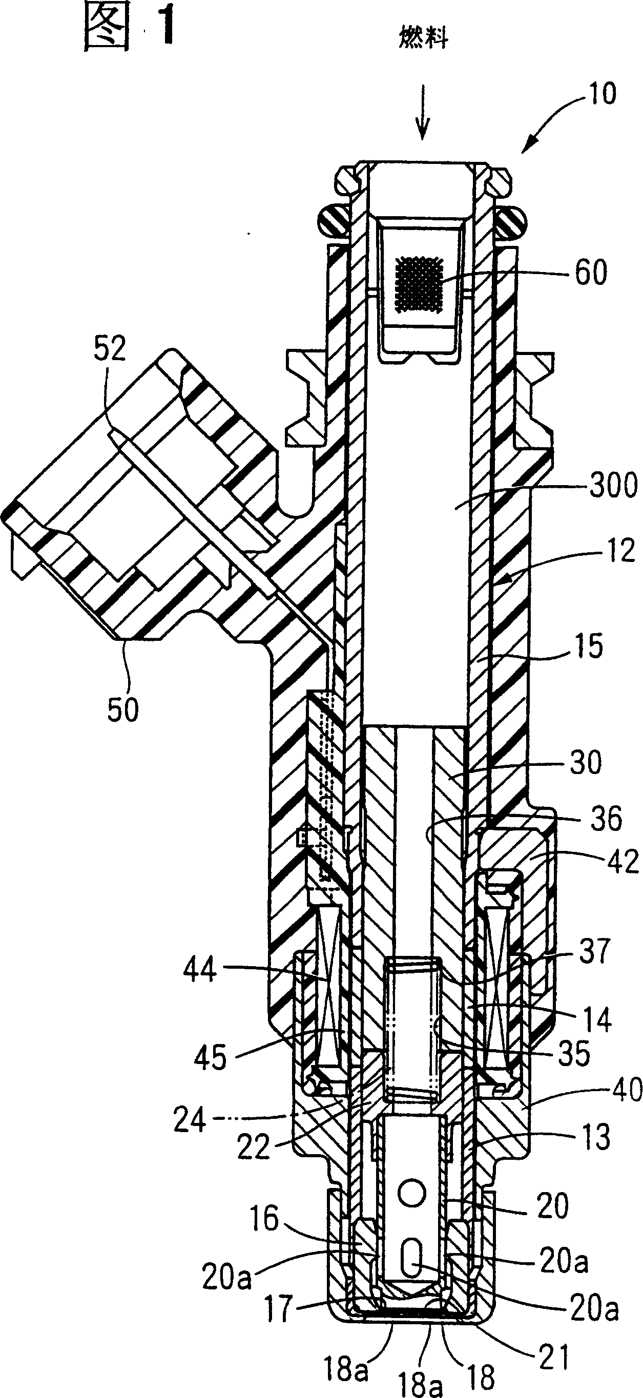
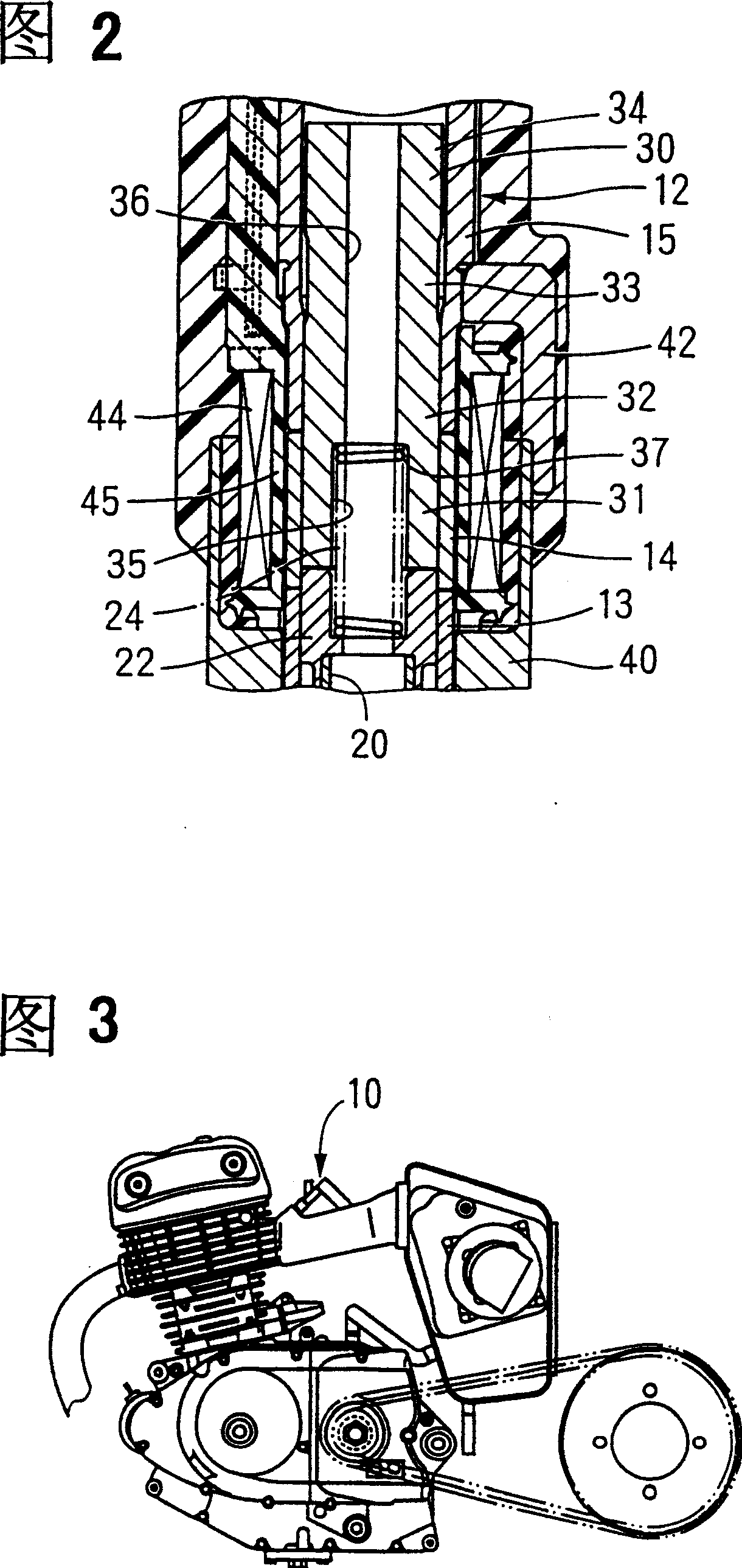
[0038] In FIG. 1 , a fuel injection valve 10 according to the first embodiment of the present invention is shown, which is installed in a single-cylinder engine of a two-wheeled motor vehicle shown in FIG. 3 . As shown in FIG. 1 , a tube 12 is composed of a magnetic element and a magnetoresistive element, and its shape is a cylinder. The inside of the pipe member 12 is provided with a fuel passage 300 . Inside the fuel passage 300 are housed the valve body 16 , the valve member 20 and the moving core 22 , the spring 24 serving as an urging member, and the fixed core 30 .

[0039] The pipe piece 12 has a first magnetic element 13 , a reluctance element 14 as a diamagnetic element and a second magnetic element 15 , which are sequentially arranged upward from the vicinity of the valve body 16 at the lower part in FIG. 1 . The connection between the first magnetic element 13 and the magneto-resistive element 14 and the connection between the magneto-resistive element 14 and the s...

no. 2 example

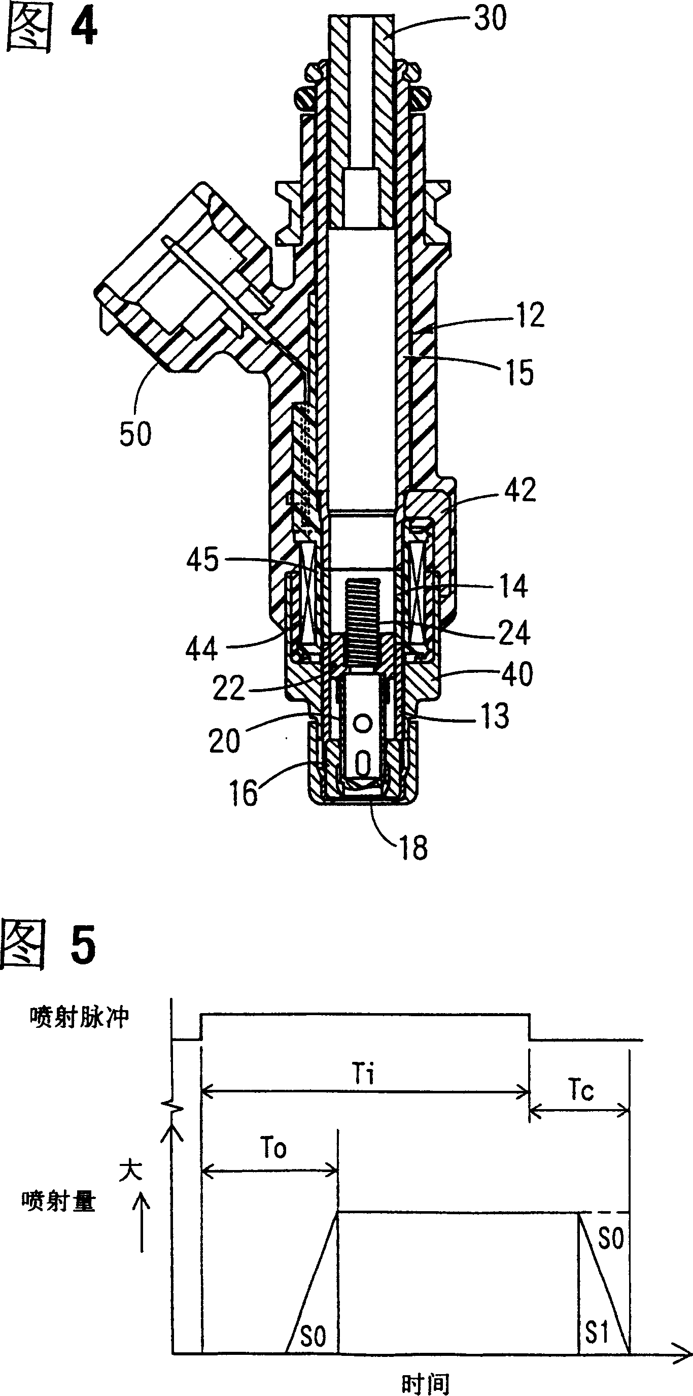
[0062] The method of adjusting the dynamic injection quantity according to the second embodiment will be described below with reference to FIGS. 10 to 13 . The method of adjusting the dynamic injection quantity according to the second embodiment is applicable to the structure of the fuel injection valve, which is basically the same as that of the first embodiment. Fig. 13 is a flowchart showing a method of adjusting the dynamic injection quantity according to the second embodiment.

[0063] As shown in FIG. 10A, the case member 200 is made of a resin material by connecting the magnetic elements 40 and 42 and the coil 44 (step 400 in FIG. 13). The magnetic elements 40 and 42 and the coil 44 are members provided on the periphery of the tube 12 . Further, as shown in FIG. 10B , the tube 12 is formed by welding the first magnetic member 13 , the magnetoresistive element 14 and the second magnetic member 15 to each other.

[0064] As shown in FIG. 11A, the pipe member 12 is press...

no. 3 example

[0072] A third embodiment of the present invention will be described with reference to FIG. 14 . The same reference numerals as in the first embodiment denote elements with substantially similar functions.

[0073] A fixed core 70 is press fit into the tube 12 . On the inner periphery of the fixed core 70, a plurality of protrusions or an annular protrusion 72 are arranged at circumferential intervals, which are radially protruded inwardly by cold forging or stamping. A single or a plurality of protrusions 72 constitute a protrusion portion. The inner diameter of the fixed core 30 becomes smaller at the protrusion 72 by which the spring 24 is restrained.

[0074] In the fuel injection valve according to the third embodiment, the static and dynamic injection quantities are simultaneously determined by adjusting the gap between the movable core 22 and the fixed core 30 to a predetermined value.

[0075] Furthermore, when the fixed core 70 is press-fitted into the pipe member ...


PUM


Abstract

A fixed core 30 is fixed to a cylindrical member 12 by being pressed and inserted to a nonmagnetic member 14 of the cylindrical member 12, and inside of a secondary magnetic member 15. An inner diameter wall of the fixed core 30 has a larger diameter part 35 and a smaller diameter part 36. A step 37 is formed on the border between the larger diameter part 35 and the smaller diameter part 36. One end of a spring 24 is engaged with the step 37 and the other end is engaged with the movable core 22. The spring 24 energizes the movable core 22 and a valve member 20 in the direction which the valve member 20 is seated at a valve seat 17. When energization to a coil 44 is on, the valve member 20 along with the movable core 22 is moved to the fixed core 30 against the energization of the spring 24, and a contact 21 is separated from the valve seat 17. Thus, the fuel is injected from an injection hole 18a.

Description

technical field [0001] The present invention relates to a fuel injection valve for an internal combustion engine (hereinafter referred to as an engine) and a method for adjusting its injection quantity. Background technique [0002] In order to adjust the injection quantity of the fuel injection valve, it is necessary to adjust the static injection quantity and the dynamic injection quantity. The static injection volume is determined by the gap between the fixed core and the moving core. The dynamic injection quantity depends on the urging force of the spring to the valve member which reciprocates with the moving core. JP-A-4-231672 discloses a known adjusting tube for suppressing a spring, which is provided in a fixed core, and the pushing force of the spring is adjusted by changing the position of the adjusting tube relative to the fixed core. In the fuel injection valve disclosed in JP-A-4-231672, usually after adjusting the gap between the fixed core and the movable co...

Claims


Application Information

Patent Timeline
Patent Type & Authority Patents(China)
IPC IPC(8): F02M51/06F02M61/20
Inventor 奥山昌平杉山幸一
Owner DENSO CORP
Why Eureka
Try Eureka