

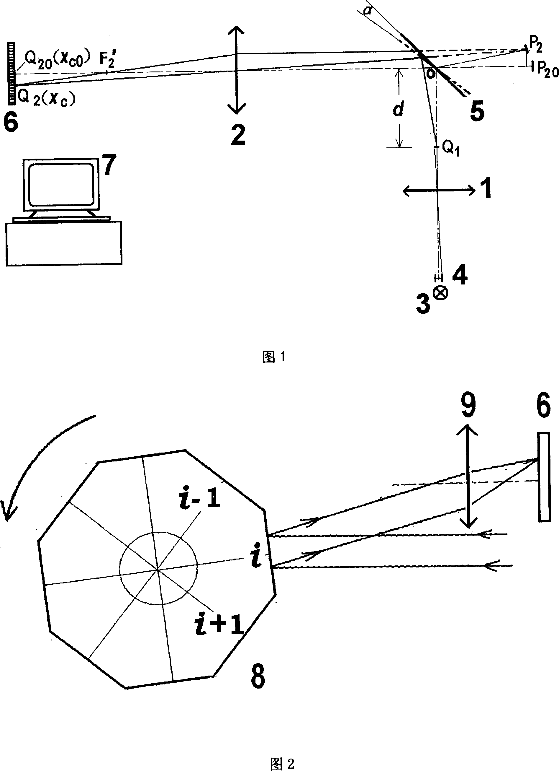
Method for measuring light-beam central position by array CCD
A center position, measuring beam technology, applied in the direction of measuring devices, optical devices, instruments, etc., can solve the problems of wide range of application requirements and difficult implementation
- Summary
- Abstract
- Description
- Claims
- Application Information
AI Technical Summary
Problems solved by technology
Method used
Image

Examples
Embodiment Construction
[0045] The method for measuring beam center position with linear array CCD described in the present invention and according to this method carry out rotating mirror angle measurement, impact circuit meter rotating mirror dynamic deflection angle measurement, displacement measurement, 0~360 degree angle measurement and linear visible spectrum Specific instructions for wavelength measurement are as follows:
[0046] 1. The method of measuring the center position of the beam with a linear array CCD
[0047] 1.1 Beam radiation power density distribution using quasi-Gaussian distribution
[0048]The Gaussian distribution is a distribution that is closer to the radiation power density distribution of the common beam cross-section, and it is also a distribution that is easier to approximate. Set the distance between the centers of adjacent pixels of the CCD detector as W (pixel spacing). Let the radiation power line density on the receiving surface be a Gaussian distribution
[00...
PUM
 Abstract
Description
Claims
Application Information