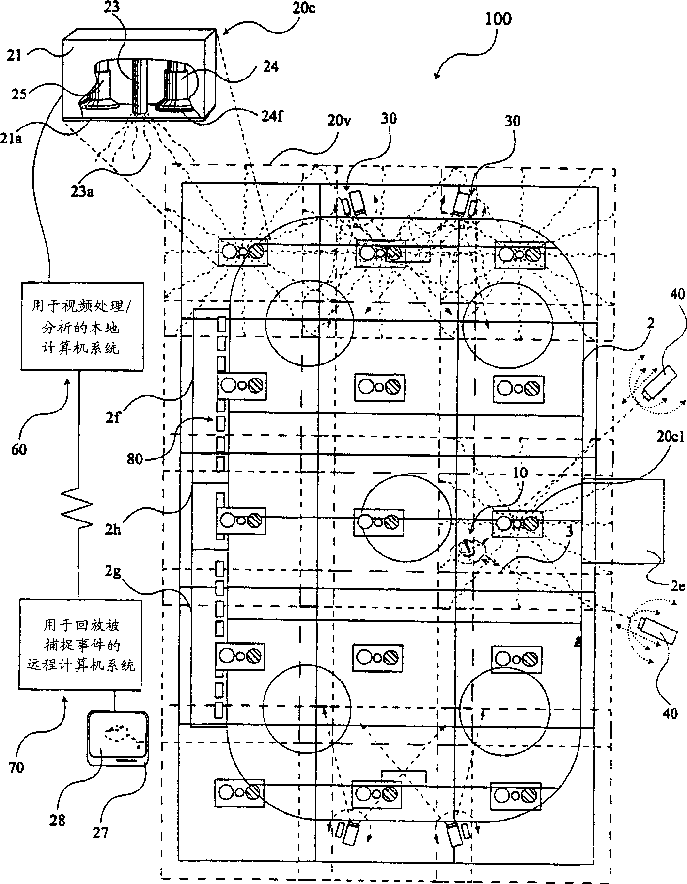
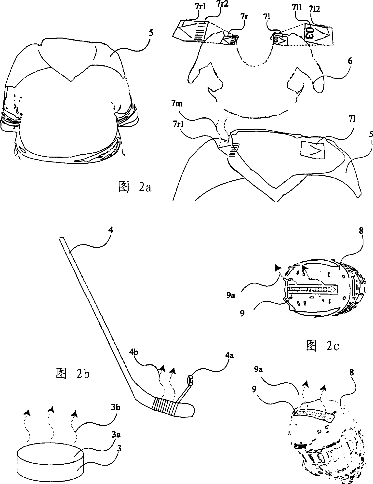
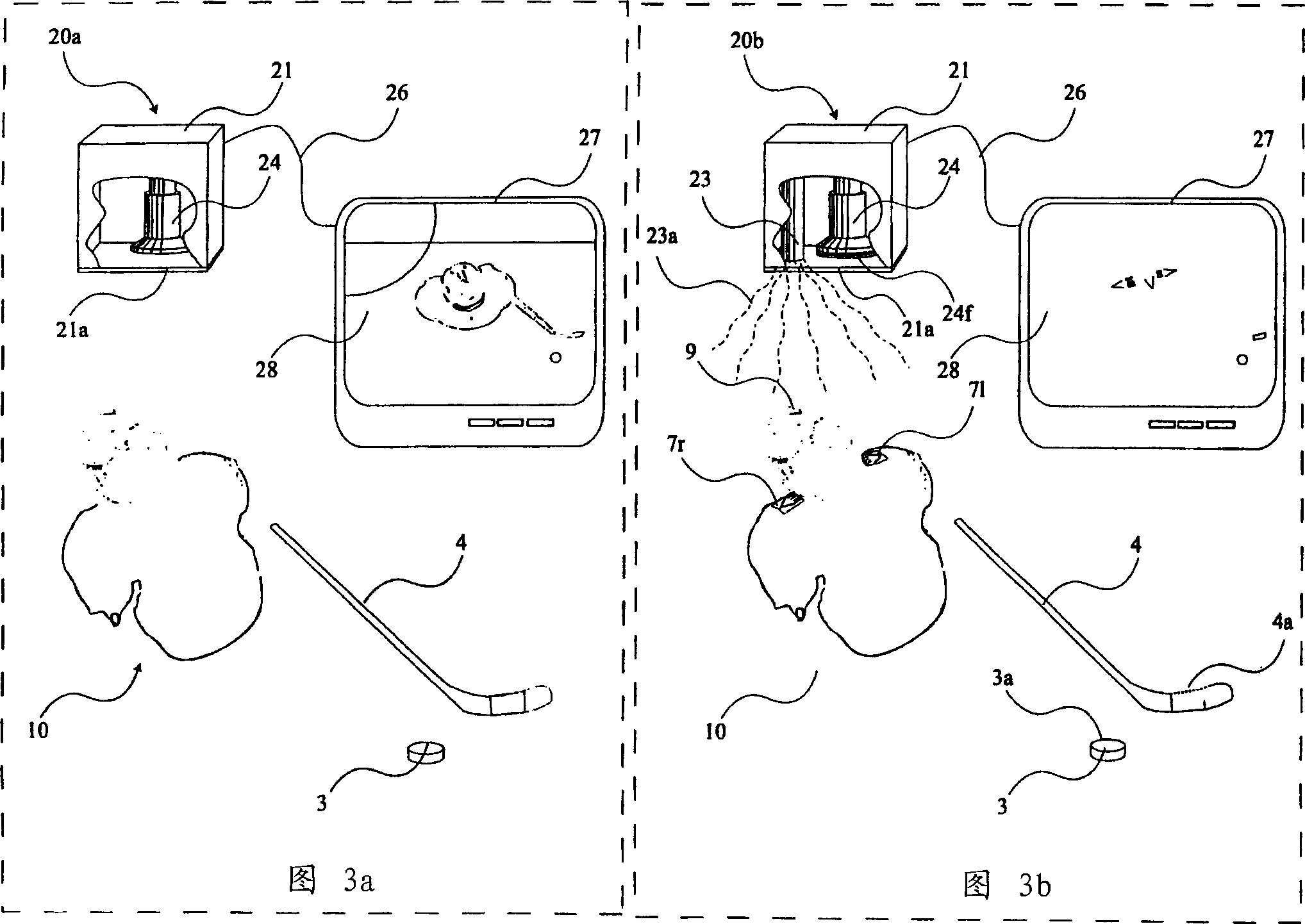
There are at least four major problems with Larson's patent. First, the amount of digital
processing required to perform real-time separation of players is vastly beyond the reach of cost-viable
computer technology today, let alone 1994's
Second, in order to perform these separations, a large amount of detail is required, resulting in increased costs resulting from the more cameras and computer systems required
Of course adding details will only further slow down the responsiveness of the system
Third, the need for one or more manipulators to initially identify and then re-identify players is extremely restrictive and costly
This requirement basically makes this patent economically unfeasible for surveillance of amateur youth sports, where the cost of the system including the running costs of human operators far outweighs the small revenue
It should be noted that this
manipulator will ideally be the parent of a youngster who is likely not familiar with all the players and who will easily find it stressful to make so many decisions in real time
This approach will also require training and retraining the
manipulator, which will also be of limited
Fourth, the type of
electronics needed to track players in real time would have to operate at a
very high frequency, which also meant that it was expensive, creating further economic disadvantages
The fifth major problem is that the system has difficulty determining the orientation of a player, for example, while Larson's invention detects the direction of a single person's movement, it cannot determine whether that player is facing forward or backward, let alone whether the player's face is turning the other way. direction
A third problem is that Abe'
s system is not suitable for tracking multiple targets with similar or identical brightness / color information that may overlap from frame to frame
The fourth issue is discussed in Abe's specification, which points out the need for the
human operator to initialize the system by selecting the part of the
video image that contains the object to be tracked, its so-called region-specific frame
Third, this invention proposes a system that functions well even when the image contains many objects or there is a lot of
noise, however, if any of these objects to be tracked is within the same image, Hashima will not be at optimum performance since at any given time the preferred orientation of the camera to the target cannot be simultaneously maintained for three sizes of spread-out targets
However, there are many situations in which it is necessary to track the precise continuous motion of all tracked objects as the objects move within a predetermined area.
While it is conceivable that this invention could continuously transmit interrogation signals and receive location
signal responses to all targets, it can be seen that this amount of information would unacceptably limit the motion resolution of the system
third, such circuit-based systems do not understand a target's orientation relative to its direction of motion
the second limitation is that the system does not attempt to uniquely identify the targets it detects
Thus, while it is capable of determining the trajectory vectors of individual targets, it does not meet the requirement of determining the unique identity of each target as it passes by, nor does it disclose such a method
the third limitation concerns the ability to track multiple targets simultaneously within the same
horizonA fourth limitation concerns the system's inability to pick objects from the background when there is not a large enough color or brightness difference between the background and the object
[0011] 1. If a
tracking system such as Larson et al. does is only based on a pixel-by-pixel comparison to try to distinguish objects from their backgrounds, then the video system must have a higher resolution to be accurate, and the resulting computer
Processing time prevents real-time operation
[0012] 2. If tracking systems such as Abe's do reduce
processing time by performing averaging techniques based on separate color and brightness information, then, especially due to color convergence between multiple objects and their backgrounds or due to Accuracy is compromised by significant fluctuations in light conditions
this implies that each tracked target must have its own camera, greatly reducing the
efficacy of these techniques for tracking multiple targets and / or tracking large horizons
[0013] 3. If a
tracking system such as Lowery et al. uses two perspective cameras and image displacement techniques to capture 3D trajectory information, it reduces
image processing requirements but loses important
video image details
However, Hashima faced significant problems when attempting to determine three-dimensional dimensional information from a single two-dimensional image, the requirements of which he had to follow, and his
compositing technique made markings of objects over a wider
field of view occasionally invisible or at least in tracking multiple fast-moving targets within a
wide field of view where the perspective of the tracking camera varies significantly
[0015] 5. All video / cameras based on techniques like Larson, Abe, hashima and lowery are prone to error if they track multiple targets whose paths will intersect and / or collide Only Larson specifically predicts this type of multi-target tracking , and proposes the use of human manipulators to resolve target overlap such manipulators are cost prohibitive and are also limited in their ability to keep up with fast moving targets in real time
[0020] 10. All video / camera-based solutions, no matter what technology they use, have difficulty picking up fast-moving targets whose color or brightness is very close to other tracking targets or the background of the image


