
Cyclic treating system of working liquid for electrospark machining

A treatment system and working fluid technology, applied in the field of circulating treatment systems, can solve the problems of low filtration efficiency, inability to filter non-magnetic processing slag, shorten the service life of processing working fluid, etc., and achieve low cost, scientific design and convenient operation Effect

Inactive Publication Date: 2002-02-06
SHENZHEN UNIV +1
View PDF0 Cites 14 Cited by
  • Summary
  • Abstract
  • Description
  • Claims
  • Application Information

AI Technical Summary

Problems solved by technology

The disadvantages in the actual use of this system are: within the effective life of the processing working fluid, processing slag and mixed powder coexist, which directly results in shortening the service life of the processing working fluid, and the quality of the processing working fluid is not good. Stable, easy to damage the machined surface
The working fluid treatment system of Polymide (Makino) Co., Ltd. in Japan is more advanced than that of Sodick. It can be filtered on-line. It does not need to replace the working fluid for rough and fine machining, and the equipment is simple. However, it cannot filter non-magnetic processing slag and control powder particles. Defects such as low diameter and low filtration efficiency

Method used

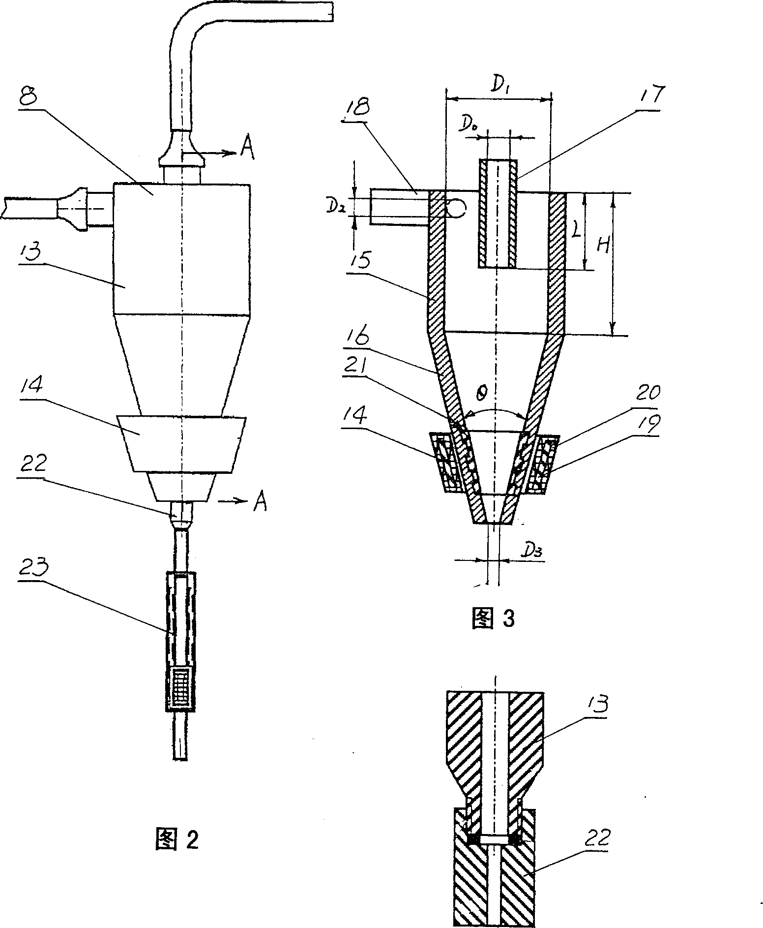

Image

  • Cyclic treating system of working liquid for electrospark machining
  • Cyclic treating system of working liquid for electrospark machining
  • Cyclic treating system of working liquid for electrospark machining

Examples


Embodiment 1

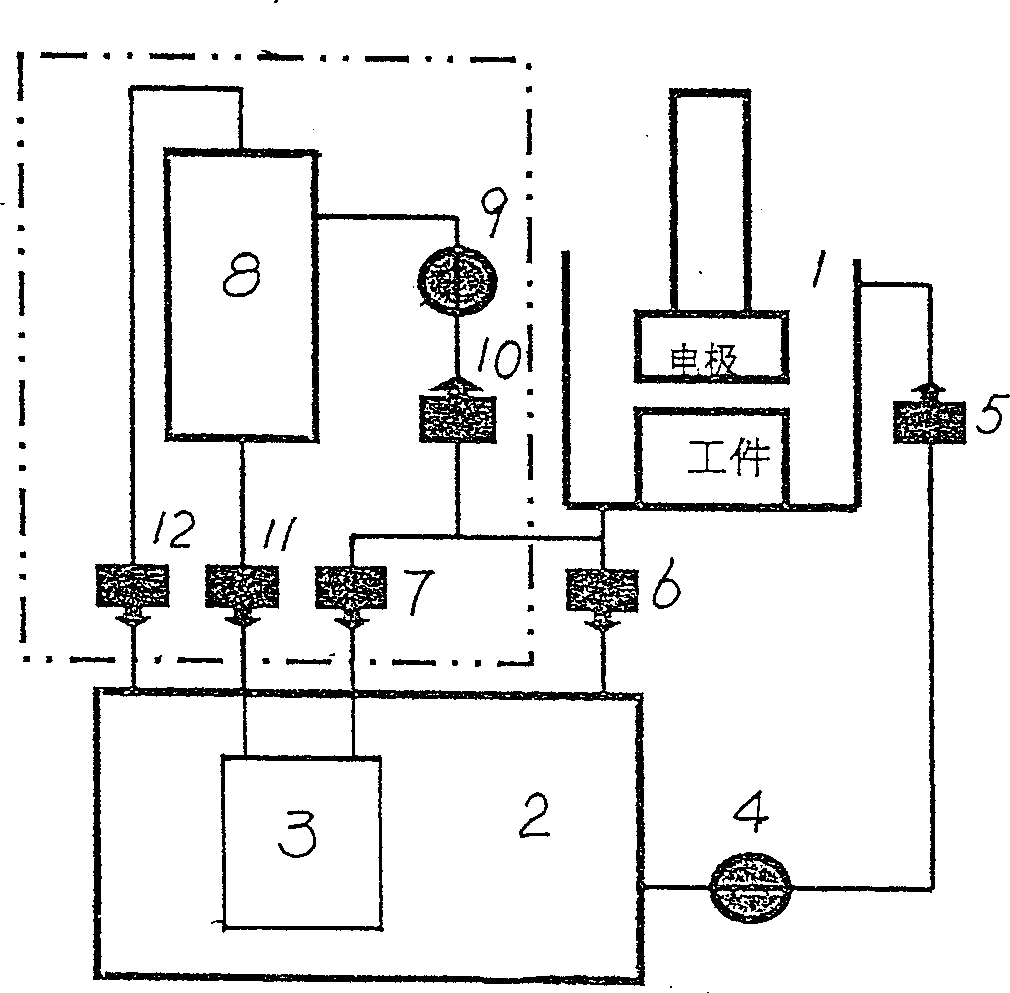
[0045] Example 1: from figure 1 It can be clearly seen that the processing system of the EDM working fluid includes: a liquid tank 1 for processing workpieces, a liquid storage tank 2 connected to the input port of the working fluid of the liquid tank 1 through a pipeline, and the input pipeline is A pump 4 and a control valve 5 are provided; the bottom of the liquid tank 1 is provided with a three-way pipe, and the parallel pipes through the three-way pipe are respectively connected to the oil tank 2 and the filter 3, and the parallel pipes are equipped with control valves 6 , 7; the filter 3 communicates with the liquid storage tank 2, and is characterized in that: on the pipeline connected between the liquid tank 1 and the filter 3, an underflow type magnetic hydrocyclone 8 is connected, and the underflow type magnetic force fluid A pump 9 and a control valve 10 are provided on the pipeline connecting the hydrocyclone 8 and the liquid tank 1, and the underflow magnetic hydr...

Embodiment 2

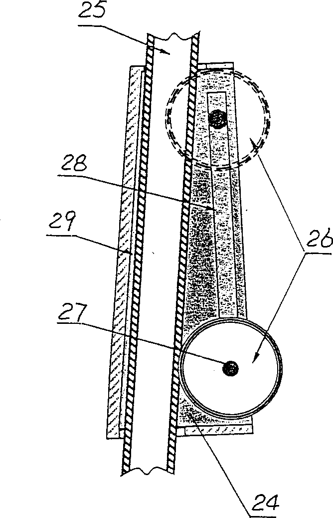
[0047] Embodiment 2: The composition of the treatment system of the EDM working fluid of this embodiment is the same as that of Embodiment 1, the difference being: in order to meet the variation of the size of the sediment port of the hydrocyclone 13, the sediment pipe of the hydrocyclone 13 The mouth is equipped with a stepless diameter changing device 23 that can quickly replace the diameter of the sediment mouth (see Figure 5 ), the infinitely variable caliber device 23 is made up of a pipe frame 24 and a roller 26 for extruding the flexible pipe 25. It can roll up and down along the rail groove 28, and a pipe groove 29 for inserting the sediment mouth hose 25 is offered at an angle with the rail groove 28. Use the roller 26 to roll up and down to adjust the squeezed degree of the hose 25. When the roller 26 is at the bottom, the hose 25 is not squeezed, and its original diameter remains unchanged; The pipe 26 is completely squeezed flat, and its caliber size becomes zero...


PUM

PropertyMeasurementUnit
Taperaaaaaaaaaa
The inside diameter ofaaaaaaaaaa

Abstract

A cyclic treating system for the working liquid used for electrospark machining is composed of liquid tank, oil tank, filter, connecting pipelines, and the pumps and control valves in the pipelines, and features that an under-flowing magneto-hydraulic cyclone separator is parallelly connected with the pipeline between liquid tank and filter. It can separate out more than 85% of ferromagnetic or non-ferromagnetic scrap from said working liquid in in-line mode.

Description

technical field [0001] The invention relates to a circulation treatment system of machining working fluid, in particular to a circulation treatment system of electric discharge machining working fluid suitable for the field of large-area electric spark mirror finishing. Background technique [0002] In the 1990s, in the field of international EDM, a kind of processing fluid (referred to as mixed powder working fluid) with conductive powder added to the original processing fluid was used to carry out large-area EDM mirror finishing. During the above-mentioned process, the machining working fluid in the liquid tank cooperates with the electrode to process the workpiece in a circular manner. The traditional EDM working fluid treatment system is formed in this way: the machining working fluid is pumped from the storage tank through the pump. Pull it out and send it into the electrode processing working liquid tank, and start to participate in the processing of the workpiece by t...

Claims


Application Information

Patent Timeline
IPC IPC(8): B23H1/10
Inventor 李积彬程安运胡琳柴金龙
Owner SHENZHEN UNIV
Learn More