Valve controlled residual pressure recovering equipment for impervious desalination system

A desalination system and recovery device technology, applied in reverse osmosis, osmosis/dialysis water/sewage treatment, general water supply conservation, etc., can solve the problems of low efficiency, complicated devices, small processing capacity, etc., and achieve high control accuracy and structure Simple, highly reliable results

Inactive Publication Date: 2002-04-10
TIANJIN UNIV
View PDF0 Cites 25 Cited by
  • Summary
  • Abstract
  • Description
  • Claims
  • Application Information

AI Technical Summary

Problems solved by technology

In these three designs, the main structure of the energy exchange adopts relatively complex moving parts
In addition, the efficiency of the former two is low, and the general recovery efficiency

Method used


Image

  • Valve controlled residual pressure recovering equipment for impervious desalination system
  • Valve controlled residual pressure recovering equipment for impervious desalination system
  • Valve controlled residual pressure recovering equipment for impervious desalination system

Examples


Embodiment Construction

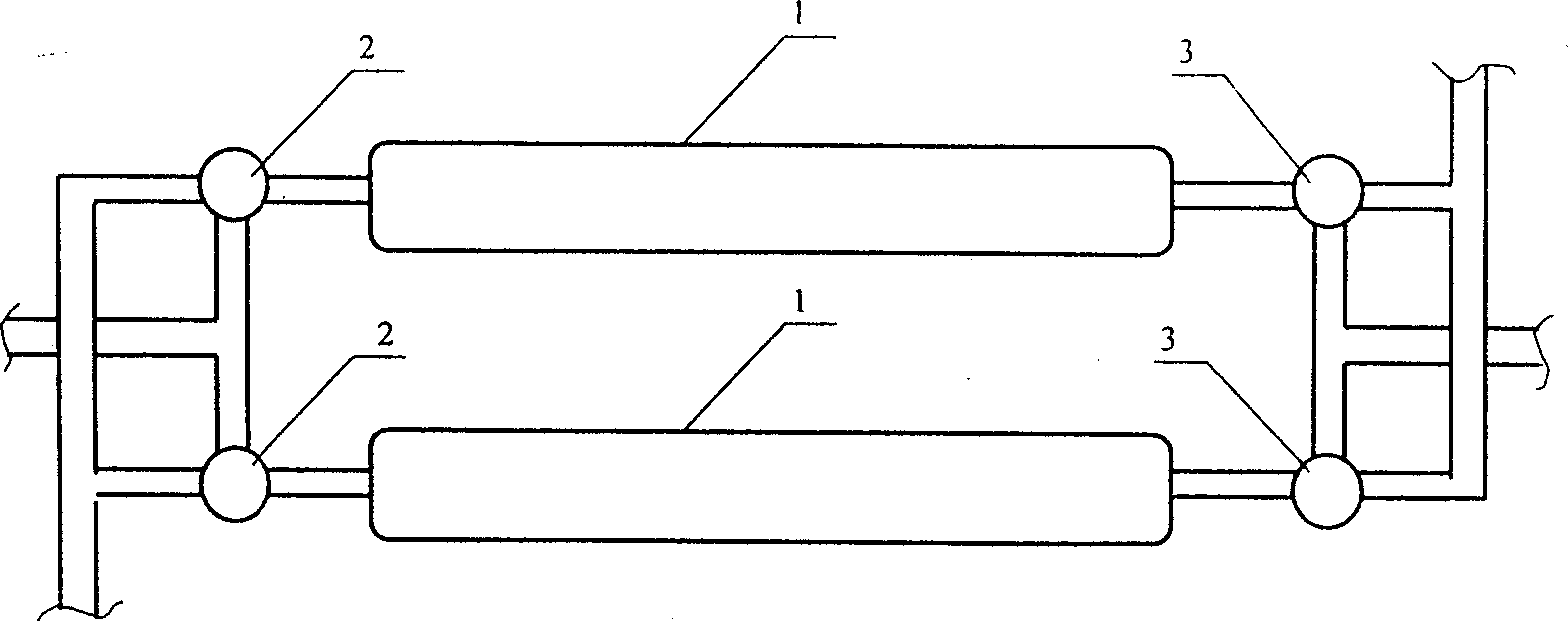
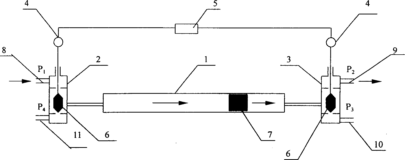
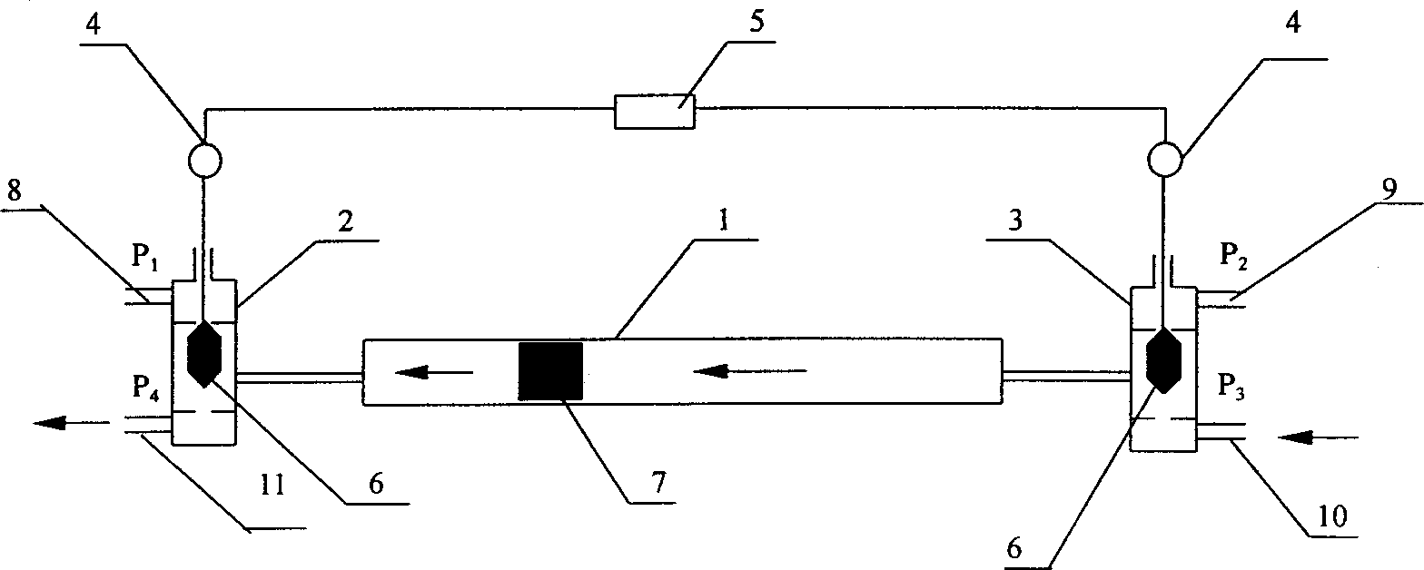
[0017] Principles and implementations are described with reference to the accompanying drawings. figure 1 A schematic diagram of the device. The principle is figure 2 shown. The residual pressure recovery device is composed of a hydraulic cylinder 1, a solenoid valve 2 at the high pressure end and a solenoid valve 3 at the low pressure end. Both solenoid valves are three-way valves. Computer 5 is accurately controlled.

[0018] The pressure of each strand of water in the system has the following relationship: P1>P2>P3>P4

[0019] When the spools 6 of the two valves are downward, the discharge concentrated brine pipe 11 and the raw seawater pipe 10 are cut off simultaneously, while the high-pressure concentrated brine pipe 8 and the pressurized seawater pipe 9 are opened. Because P1>P2, the high-pressure concentrated brine enters the hydraulic cylinder, and the seawater in the cylinder is pressed out, and the pressure of the seawater is increased to P2 at the same time, an...


PUM


Abstract

A valve-controlled residual pressure recovering equipment for impervious seawater desalinating system is composed of hydraulic cylinder, free piston in the cylinder, and high-and low-pressure three-way electromagnetic valves at both ends of the said cylinder. The position and operating time of the cores of the said electromagnetic valves are controlled by computer program. The inlet of high-pressure concentrated saline and the outlet of pressurized seawater are opened or closed simultaneously. The inlet of raw seawater and the outlet of concentrated saline are opened or closed at same time. Its advantages are simple structure, high reliability,and high efficiency of recovering residual pressure (up to 70-90%).

Description

technical field [0001] The invention relates to a valve-controlled hydraulic cylinder residual pressure recovery device for concentrated brine in a reverse osmosis desalination system. It is an innovation of a liquid residual pressure energy recovery device. Background technique [0002] Liquid residual pressure recovery devices currently include hydraulic turbine type, hydraulic type and pressure exchange type. In these three designs, the main structure of the energy exchange adopts relatively complicated moving parts. In addition, the efficiency of the former two is low, and the general recovery efficiency is between 30% and 50%, while the processing capacity of the latter is relatively small. For a large industrial system, many unit devices are often used in parallel, resulting in a of complication. [0003] In the reverse osmosis desalination process of seawater or brackish water, the residual pressure of the discharged concentrated brine i...

Claims


Application Information

Patent Timeline
IPC IPC(8): B01D61/10C02F1/44
CPCY02A20/131Y02A20/144
Inventor 王世昌王宇新徐世昌王志管山徐晅阔
Owner TIANJIN UNIV
Why Eureka
Try Eureka