Device for preventing explosions in electrical transformers

A technology of electronic transformers and transformers, applied in transformer/inductor components, transformer/inductor casings, transformer/inductor cooling, etc.

Inactive Publication Date: 2002-04-24
菲利普·马尼耶
View PDF1 Cites 8 Cited by
  • Summary
  • Abstract
  • Description
  • Claims
  • Application Information

AI Technical Summary

Problems solved by technology

However, the explosion of the transformer casing due to the increase in inter

Method used


Image

  • Device for preventing explosions in electrical transformers
  • Device for preventing explosions in electrical transformers
  • Device for preventing explosions in electrical transformers

Examples


Embodiment Construction

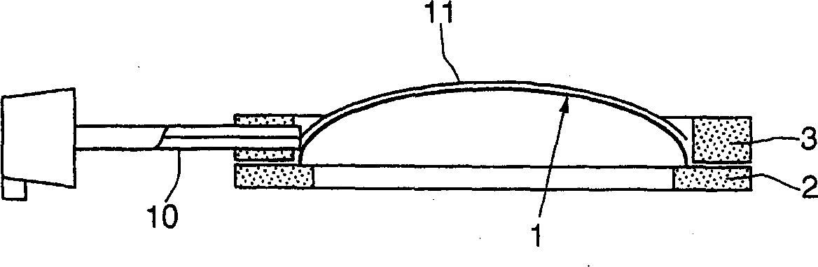
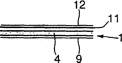
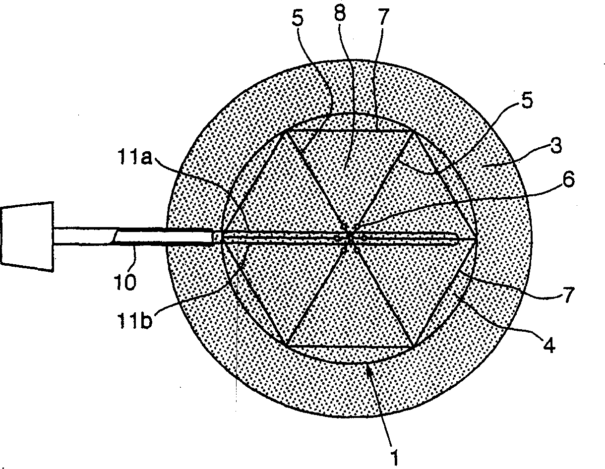
[0035] like Figure 1a , Figure 1b ,and figure 2 As shown, the rupture element 1 has the shape of a dome that protrudes on the downstream side and is used to fit a discharge hole (not shown) containing an insulating fluid housing. The rupture element 1 comprises a holding element 4 in the form of a thin metal sheet, for example made of stainless steel, aluminium or an aluminium alloy. The holding element 4 is tightly clamped between the two disk-shaped flanges 2 , 3 . The rupture element 1 comprises, in addition to the holding element 4, a sealing liner 9 arranged on the upstream side, in other words, covering the concave side of the holding element. For example, the liner 9 is based on polytetrafluoroethylene.

[0036] The holding element 4 is provided with radial lines 5 dividing it into six parts. This radial line 5 is formed hollowly in a portion of the thickness of the holding element 4 so that the rupture occurs without fragments by the holding element 4 tearing al...


PUM


Abstract

The invention concerns a device for preventing explosions in an electrical transformer comprising a vessel filled with a fuel cooling fluid, and means for decompressing the transformer vessel. The decompressing means comprise a rupture element (1) with an incorporated explosion detector provided with a retaining part (4) including first zones with reduced thickness relative to the rest of the retaining element (4) and capable of being torn off without being fragmented when said element (1) is ruptured, and second zones with reduced thickness relative to the rest of the retaining element (4) and capable of bending without getting torn off when said element (1) is ruptured. Said rupture element (1) is capable of being ruptured when the pressure inside the vessel exceeds a predetermined ceiling. The signal of the explosion detector integrated in the rupture disc triggering a cooling system and preventing oxygen from coming in contact with the explosive gases generated by the electric arc by contact with oil.

Description

technical field [0001] The present invention relates to the field of preventing explosions of electronic transformers which are cooled by a large amount of flammable fluid. Background technique [0002] Transformers have losses in the windings as well as in the core, and for this reason the heat generated must be dissipated. Therefore, high power transformers are typically cooled using a fluid such as oil. The oil used is insulating and can ignite at temperatures above 140°C. Since transformers are very expensive components, special care must be taken to protect them. [0003] Insulation faults first create a strong arc which causes the electronic protection system to act, tripping the supply relay of the transformer (circuit breaker). The arc also leads to the necessary dissipation of energy, which produces the release of gases from the breakdown of the insulating oil, especially hydrogen and acetylene. [0004] After the gas has been released, ...

Claims


Application Information

Patent Timeline
IPC IPC(8): H01F27/02H01F27/00H01F27/14H01F27/40
CPCH01F27/14H01F27/402
Inventor 菲利普·马格尼尔
Owner 菲利普·马尼耶
Why Eureka
Try Eureka