
Refrigerant recovery device

A refrigerant recovery and refrigerant gas technology, which is applied to refrigerants, refrigerators, refrigeration components, etc., can solve the problems of increased cost of Freon gas recovery and high operating costs, and achieves low recovery cost, shortened recovery time, and continuous refrigeration. The effect of agent recovery operations

Inactive Publication Date: 2002-05-01
岩崎 照皇
View PDF0 Cites 10 Cited by
  • Summary
  • Abstract
  • Description
  • Claims
  • Application Information

AI Technical Summary

Problems solved by technology

[0003] As mentioned above, the conventional recovery device must have a large-scale heat exchanger—a cross-fin-shaped condenser, so it becomes a large-scale equipment. In addition, because the operation cost is also high, the recovery cost of Freon gas increases. becomes a difficulty

Method used


Image

  • Refrigerant recovery device
  • Refrigerant recovery device
  • Refrigerant recovery device

Examples


Embodiment Construction

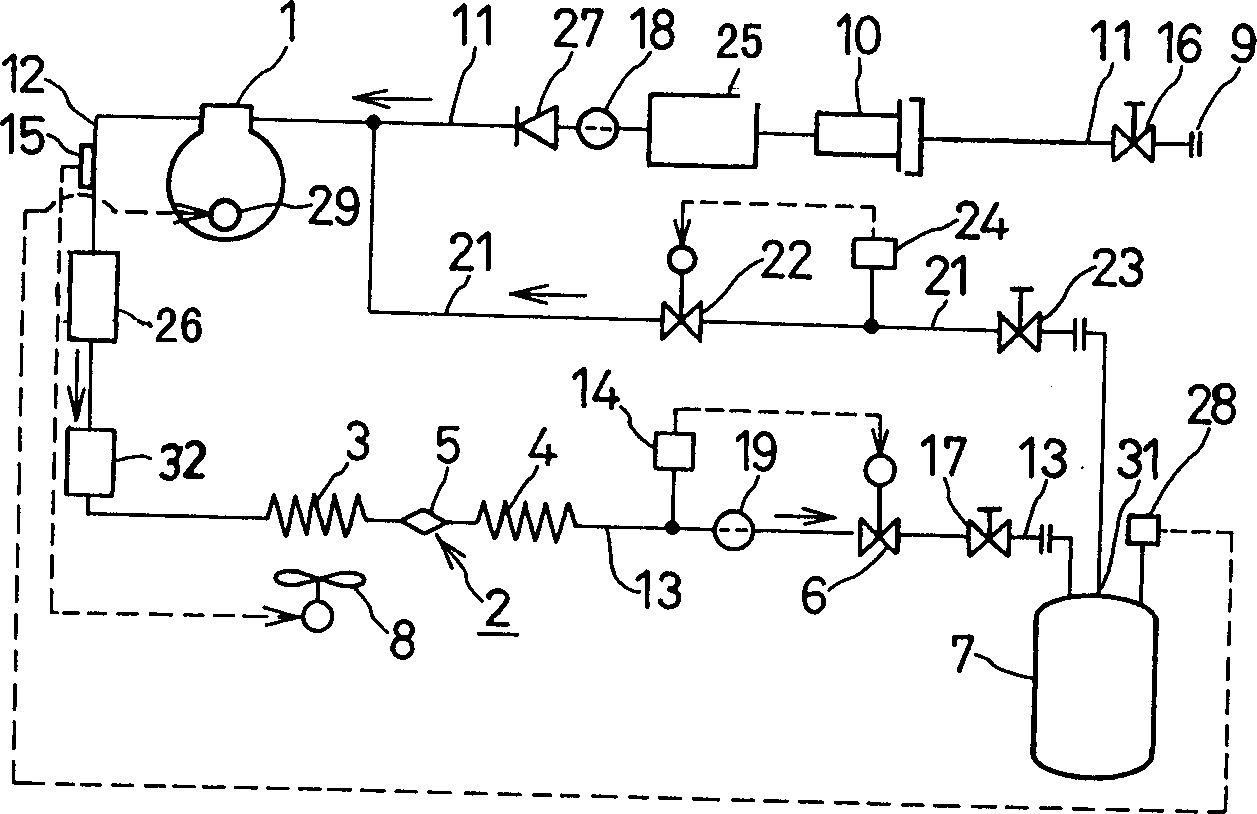
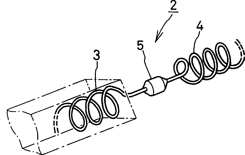
[0020] Hereinafter, preferred examples of embodiments of the present invention will be described with reference to the drawings. figure 1 It is a schematic circuit diagram of the refrigerant recovery device according to the first embodiment of the present invention. in addition, figure 2 yes figure 1 It is a perspective view of the heat exchange device 2 in the refrigerant recovery device shown.

[0021] figure 1 The shown refrigerant recovery device has a compressor 1, a heat exchange device 2, a solenoid valve 6 and a refrigerant recovery tank 7 as main equipment, and these devices are connected by refrigerant pipelines of a suction pipe 11, a discharge pipe 12 and a liquid pipe 13. Connected to form a series circuit, thereby forming a device for effectively recovering the refrigerant - Freon gas.

[0022] Moreover, the above-mentioned refrigerant recovery device is equipped with a gas pipe 21 inserted with a solenoid valve 22, and becomes a bypass with respect to the a...


PUM


Abstract

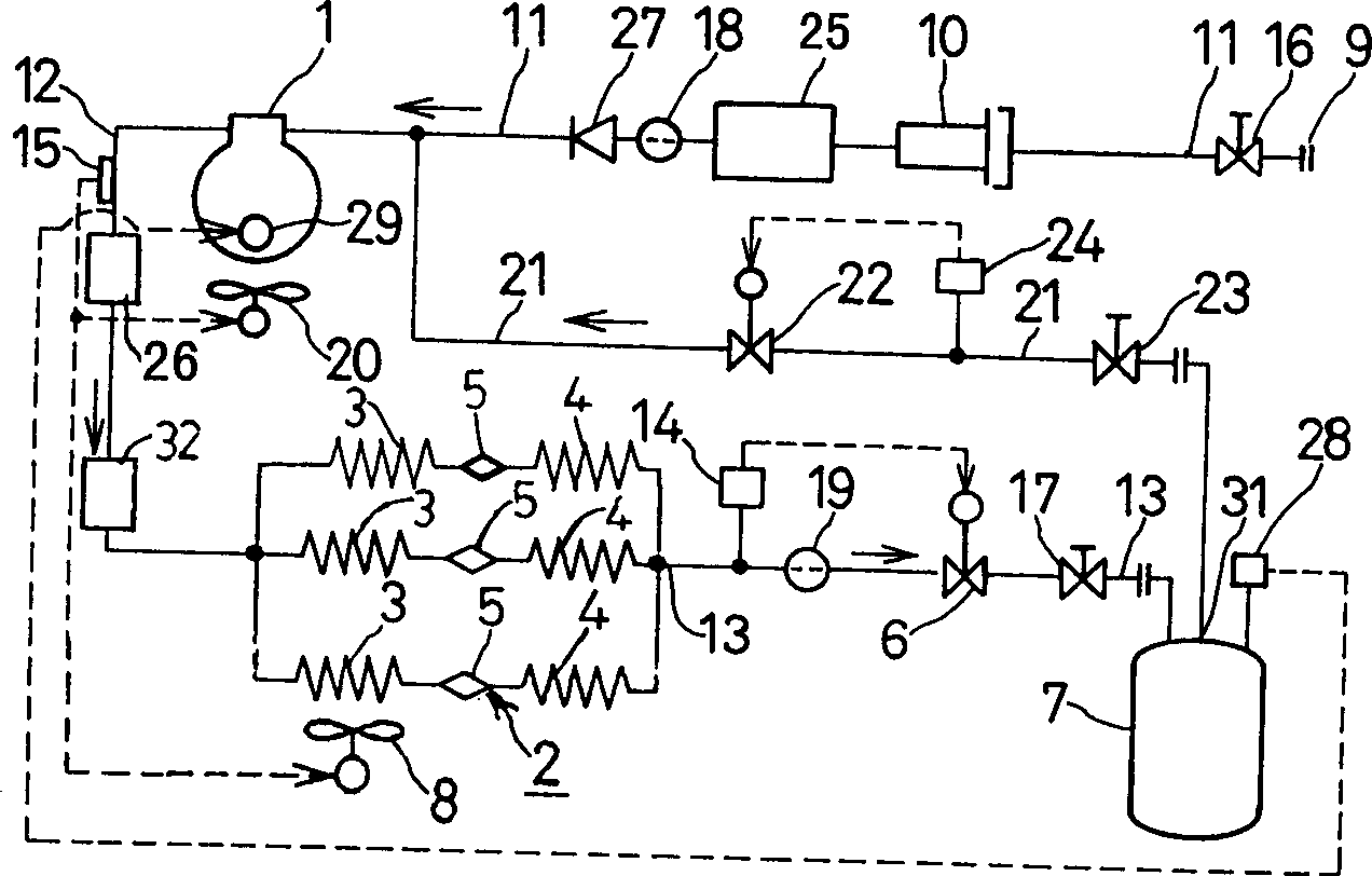
A refrigerant recovery device comprises a compressor 1 which draws in chlorofluorocarbons gas. Chlorofluorocarbons gas that has increased pressure and temperature by being discharged from the compressor 1 is conducted through a heat exchange device 2 to become liquid refrigerant. The liquid refrigerant is conducted by a liquid pipe 13 to a refrigerant recovery tank 7. Gas of the refrigerant inside the refrigerant recovery tank 7 is conducted to the compressor 1 by a gas pipe 21. The heat exchange device 2 comprises the first helical piping 3 formed by winding a small diameter heat transfer pipe, a large diameter tube 5 with a cross-sectional area larger than the previous heat transfer pipe and the second helical, small-diameter piping 4 with a structure similar to the first helical small-diameter piping 3, these elements being connected in serial as a single unit, or alternatively the heat exchange device comprises two or more single units connected together. The liquid pipe 13 comprises a solenoid valve 6 that is controlled by a pressure sensor 14 to open at a preset upper value and to close at a preset lower value. The gas pipe 12 comprises a solenoid valve 22 that is controlled by a pressure sensor 24 to open at a preset upper value and to close at a preset lower value. The present invention provides a refrigerant recovery device that is cheap, compact and is portable and easy to operate for inexpensively recovering chlorofluorocarbons.

Description

technical field [0001] The present invention relates to a refrigerant recovery device for economically and effectively recovering Freon gas, which is a main component of refrigerant used in air compressors for automobiles, houses, etc., and other equipment. Background technique [0002] It is well known that if Freon gas is released into the atmosphere, it will have a bad impact on the earth's environment. Therefore, taking the case of discarded automobiles as an example, in order to reuse Flon gas without releasing it into the atmosphere, it is common to recover Flon gas from the refrigerant line. In the past, in order to recover Freon gas, it was extracted from the recovered refrigerant system and sent in liquid form to recovery containers such as high-pressure gas cylinders. At this time, compressors and condensers are indispensable components in the recovery device. [0003] As mentioned above, the conventional recovery device must have a large-scale heat exchanger—a cr...

Claims


Application Information

Patent Timeline
Patent Type & Authority Applications(China)
IPC IPC(8): F25B45/00F28D1/047
CPCF25B45/00F25B2600/2521F25B2345/006F25B41/20
Inventor 岩崎照皇原隆雄
Owner 岩崎 照皇
Learn More