Filmforming method and device
A film-forming method and technology for a film-forming device, which can be applied to devices for applying liquid to surfaces, coatings, pre-treatment surfaces, etc., can solve problems such as spending a lot of time
- Summary
- Abstract
- Description
- Claims
- Application Information
AI Technical Summary
Problems solved by technology
Method used
Image

Examples
no. 1 Embodiment approach
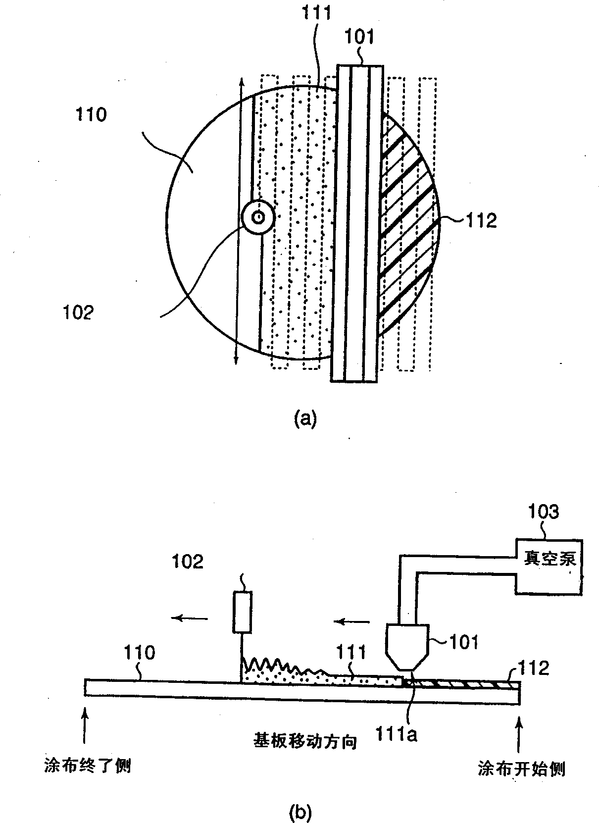
[0026] figure 1 It is a schematic diagram showing the schematic configuration of the film forming apparatus in the first embodiment of the present invention. figure 1 (a) is a plan view of the film forming apparatus, figure 1 (b) is a sectional view. The film forming apparatus can simultaneously perform a liquid film forming process and a drying process.
[0027] First, a structure for forming a liquid film in a film forming apparatus will be described. like figure 1 As shown in (a) and (b), the protective film dripping nozzle 102 and the nozzle moving mechanism (not shown in the figure) for moving the protective film dripping nozzle 102 in the y direction (the horizontal direction of the paper) and a diameter of 200 mm The substrate 110 to be processed is provided with a substrate to be processed, and a substrate to be processed moving stage (not shown in the figure) that moves the substrate to be processed 110 in the x direction is constituted.
[0028] Next, the struct...
no. 2 Embodiment approach
[0038] The device configuration of this embodiment is the same as that described in the first embodiment figure 1 The apparatus shown is the same, so the description of the apparatus is omitted. The drying process will be explained.
[0039] First, as in the first embodiment, a chemical solution is dropped onto the substrate 110 to be processed, and the formation of the liquid film 111 is started.
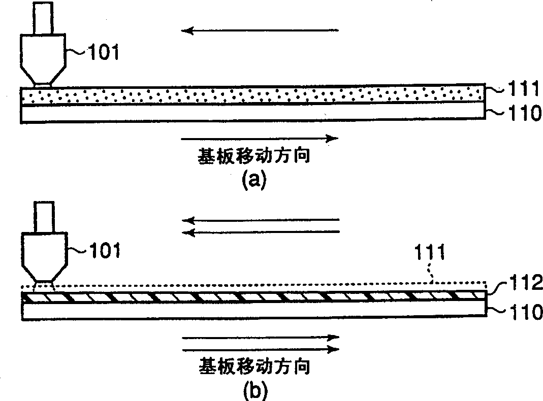
[0040]With the movement of the substrate to be processed 110, the suction port of the suction nozzle 101 connected to the vacuum pump 103 sucks the solvent atmosphere on the liquid film 111 on the substrate to be processed 110, and the first drying process is started.
[0041] Even after the suction nozzle 101 passes through the entire surface of the liquid film 111, from the +x side (coating start side) to the -x side (coating end side), a large amount of solvent remains in the liquid film 111, and the thickness of the liquid film 111 is 10μm( image 3 (a)).
[0042] As the se...
no. 3 Embodiment approach
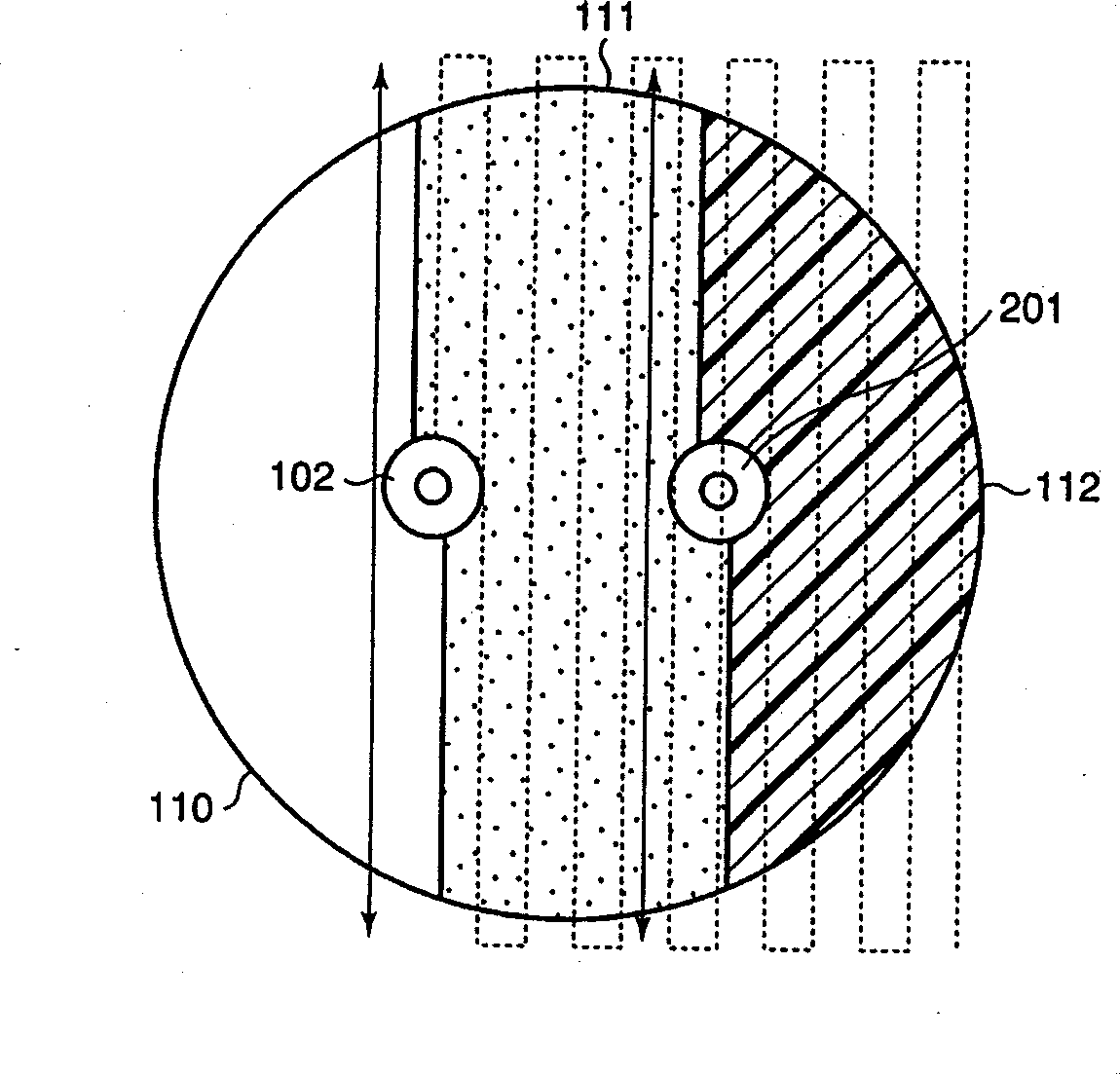
[0047] The device configuration of this embodiment is the same as that described in the first embodiment figure 1 The apparatus shown is the same, so the description of the apparatus is omitted. The drying process will be explained.
[0048] First, as in the first embodiment, a chemical solution is dropped onto the substrate 110 to be processed, and the formation of the liquid film 111 is started. However, in the present embodiment, an interlayer insulating film (LKD21: manufactured by JSR) was sequentially dropped in a line shape (shape of a single stroke), and a liquid film 111 having a thickness of 40 μm was formed on the entire surface of the substrate.
[0049] Along with the movement of the substrate to be processed 110, the suction nozzle 101 connected to the vacuum pump 103 covers the substrate to be processed 110, and the solvent atmosphere on the liquid film 111 is sucked from the suction port, from the +x side (coating start side) The first drying process was star...
PUM
| Property | Measurement | Unit |
|---|---|---|
| thickness | aaaaa | aaaaa |
| thickness | aaaaa | aaaaa |
| thickness | aaaaa | aaaaa |
Abstract
Description
Claims
Application Information
 - R&D
- Intellectual Property
- Life Sciences
- Materials
- Tech Scout
- Unparalleled Data Quality
- Higher Quality Content
- 60% Fewer Hallucinations
Browse by: Latest US Patents, China's latest patents, Technical Efficacy Thesaurus, Application Domain, Technology Topic, Popular Technical Reports.
© 2025 PatSnap. All rights reserved.Legal|Privacy policy|Modern Slavery Act Transparency Statement|Sitemap|About US| Contact US: help@patsnap.com