Optical variable image making method and its photocomposition system

A production method and imaging system technology, applied in 3D image processing, image data processing, instruments, etc., can solve the problems of difficult to form variable shape image coding effect, poor practical effect, low energy utilization rate of light source, etc.

Inactive Publication Date: 2002-05-22
SUZHOU UNIV
View PDF1 Cites 22 Cited by
  • Summary
  • Abstract
  • Description
  • Claims
  • Application Information

AI Technical Summary

Problems solved by technology

At present, there are mainly two ways to make optically variable images. One is to record holograms that form two-dimensional or three-dimensional images by light interference on a holographic dry plate. , Optically variable images with dynamic effects are very difficult; the other is laser direct writing, in which a computer controls the movement of a fine laser beam on the sample stage, and directly exposes on the surface of the photoresist to carve a continuous relief structure. The beam direct writing method has high requirements for electronic control and mechanical precision. If a grating of 10 mm × 10 mm is designed, the diameter of the focal point of the beam is 1 micron, and the operating speed is 10 mm / s, and the lithography is 500 lines The grating of / mm needs at least 80 minutes. For optically variable images with smaller grating constants and larger areas (such as optically variable images for laser anti-counterfeiting packaging materials), single laser direct writing is obviously not suitable
In U.S. Patent No. 5291317, a method for making a holographic diffraction grating pattern is disclosed. After the incident light passes through the diffraction grating, an aperture is used to block the 0-order light and high-order diffracted light, and the positive and negative first-order lights are converged on the photosensitive material. Forming a holographic diffraction grating pattern, because the light intensity of the diffraction grating is concentrated on the 0th order light, the energy utilization rate of the light source is extremely low, requiring a large power of the light source and prolonging the exposure time. At the same time, this method cannot Inserting an image input device into the optical path makes it difficult to form a variable-shape image encoding effect, and the practical effect is poor

Method used


Image

  • Optical variable image making method and its photocomposition system
  • Optical variable image making method and its photocomposition system
  • Optical variable image making method and its photocomposition system

Examples


Embodiment 1

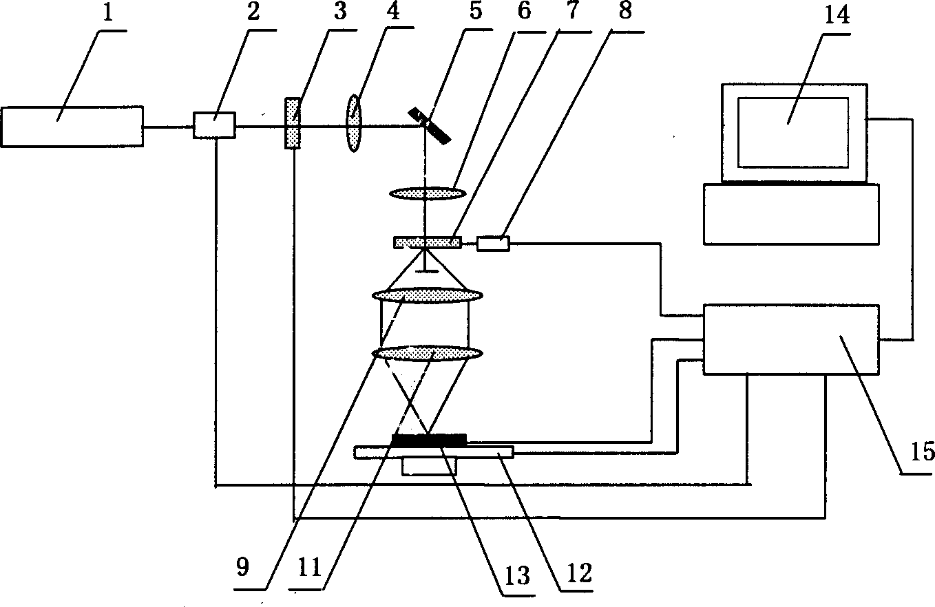
[0040] Embodiment one: see attached figure 2 As shown, a method for making an optically variable image is characterized in that: comprising the following steps, (1) imaging a shape diaphragm onto a holographic optical element 7 by a light source 1 through an optical imaging system to generate a pair of diffracted beams; (2) Converging the diffracted light beam on the recording material 13 to produce an interference fringe point; (3) moving the position of the recording material 13; (4) recording an interference fringe point; (5) repeating steps (3) and (4), until the production of the optically variable image is completed.

[0041] The optically variable image phototypesetting system of this embodiment includes an optical path system composed of a light source 1, a pre-diffraction imaging system, a holographic optical element 7, and a post-diffraction imaging system, a workbench 12 for placing recording materials 13, and a control system including a computer 14. part, the ho...

Embodiment 2

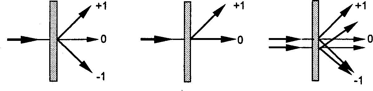
[0043] Embodiment two: see attached Figure 4 As shown, an optically variable image typesetting system includes an optical path composed of a light source 1, a photoelectric switch 2, a diaphragm 3, an imaging system before diffraction, a holographic optical element 7, an imaging system after diffraction, and a workbench for placing recording materials 13 12 and a control part 15 including a computer 14, the holographic optical element 7 is placed on the turntable 8, the diffraction front imaging system includes a mirror 5 and a lens 6, and the holographic optical element 7 converts the incident light into +1 order and 0th order light, the post-diffraction imaging system includes a lens group composed of a lens 9 and a lens 11, and an image input device 10 is arranged between the lens 9 and the lens 11.

[0044] In this embodiment, since the holographic optical element 7 with only +1 order and 0 order light is selected, the image input device 10 can be inserted into the post-d...

Embodiment 3

[0045] Embodiment three: see attached Figure 5 As shown, an optically variable image phototypesetting system has a structure similar to that of Embodiment 1, wherein, in the imaging system before diffraction, the mirror 5 adopts an x-y vibrating mirror combination, and the lens 6 adopts an F-θ mirror. In this way, when in use, the position of the recording beam can be moved through the movement of the galvanometer, reducing the range of movement of the X-Y coordinate stage.


PUM


Abstract

The production method of optical variable image includes the following steps: using a light source and utilizing imaging system to image the shape diaphragm on homographic optical element to producinga a pair of diffraction light beams; collecting the diffraction light beams on the recording material to produce interference fringe point with a certain shape; moving the position of recording material and recording next interference fringe point, repeating above-mentioned operatino until said method is completed. Said optical variable image phototype setting system includes optical circuit system formed from light source, imaging system before diffraction, homographic optical element and imaging system after diffraction, working table and control portion. Said invention can effectively utilize energy of incident light to implement production of homographic diffraction grating.

Description

technical field [0001] The present invention relates to a method for making an optically variable image and its phototypesetting system, in particular to a method for making an optically variable image by using an interference type optical head as a laser direct writing head, and using laser interference fringe points as laser direct writing points. its device. Background technique [0002] Optically variable images are composed of unit gratings with different space frequencies and grating orientations. For embossed images, they can be molded and plated with aluminum to make them reflective reproduction holograms. The human eye can directly observe the reflected diffracted light from the image against the light source. There are infinite combinations of the orientation and space frequency of the unit grating, so that the optical variable image has the optical characteristics of multiple light-variable effects such as color change, dynamic effect and...

Claims


Application Information

Patent Timeline
Patent Type & Authority Applications(China)
IPC IPC(8): G03H1/04G03H1/18
Inventor 陈林森解剑峰沈雁吴建宏胡祖元陆志伟胡元汪振华顾华俭
Owner SUZHOU UNIV
Why Eureka
Try Eureka