Engine-adjustable whirlwind generator and method for processing air-inlet hole of adjustable whirlwind generator

一种发生装置、加工方法的技术,应用在发动机元件、发动机控制、燃烧发动机等方向,能够解决流动气流流速降低等问题,达到减少空气气流阻力、制造成本不高、结构简单的效果

Inactive Publication Date: 2002-08-07
HYUNDAI MOTOR CO LTD
View PDF0 Cites 12 Cited by
  • Summary
  • Abstract
  • Description
  • Claims
  • Application Information

AI Technical Summary

Problems solved by technology

Due to such a bent position, most of the air flow passing through the bypass pipe 106 is blocked, so the bent position reduces the flow velocity of the flowing air stream.

Method used


Image

  • Engine-adjustable whirlwind generator and method for processing air-inlet hole of adjustable whirlwind generator
  • Engine-adjustable whirlwind generator and method for processing air-inlet hole of adjustable whirlwind generator
  • Engine-adjustable whirlwind generator and method for processing air-inlet hole of adjustable whirlwind generator

Examples


Embodiment Construction

[0024] Preferred embodiments of the present invention will be described below in conjunction with the accompanying drawings. In the following description and drawings, the same numerals are used on the same or similar components, so the description of the same or similar components will be omitted.

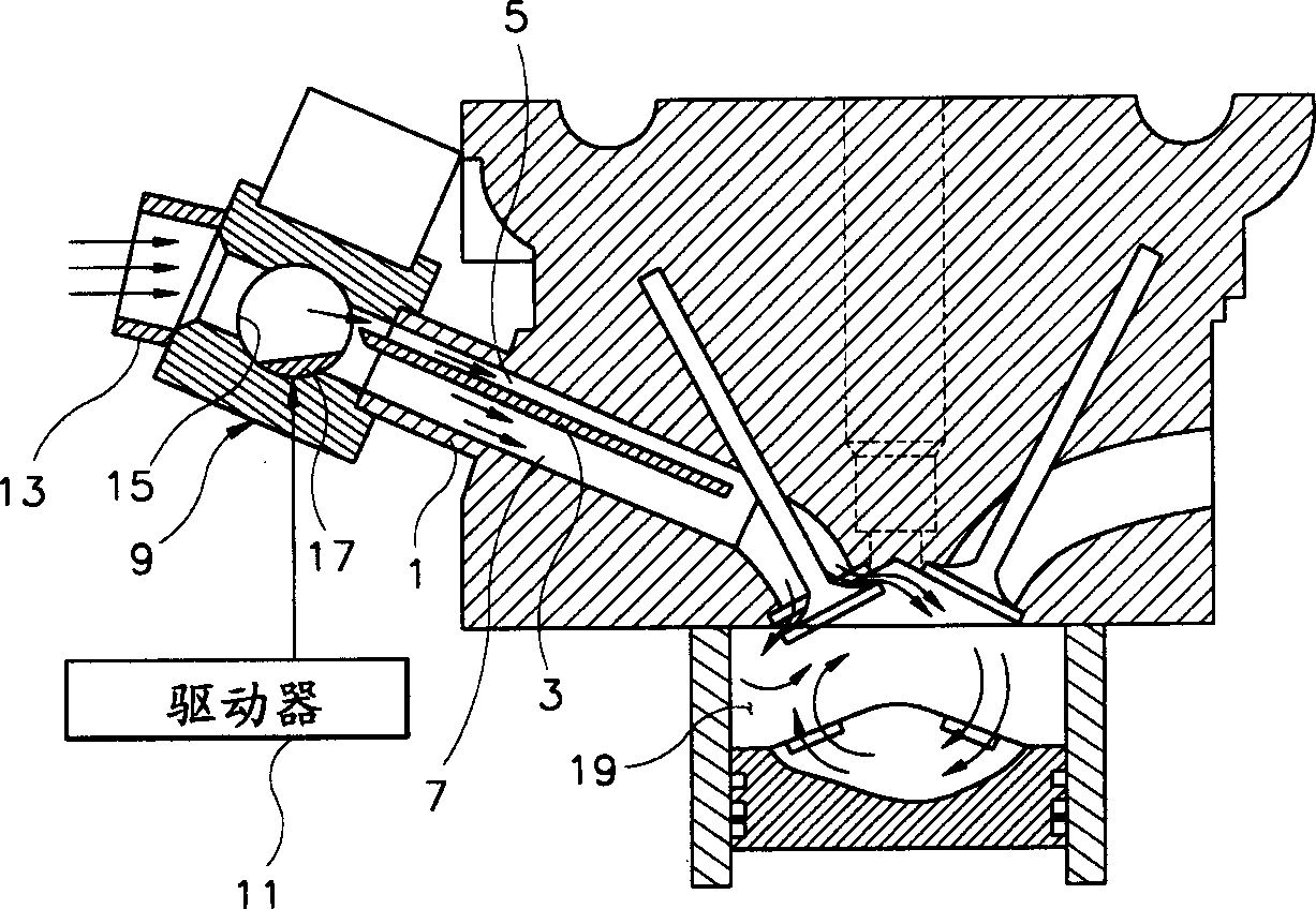
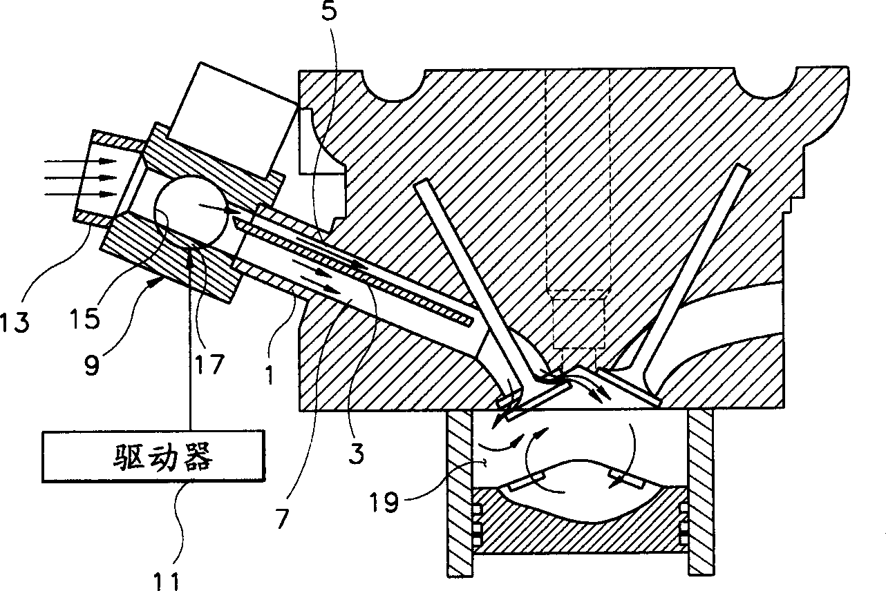
[0025] According to the present invention, figure 2 A variable swirl generating device for an engine is shown. Such as figure 2 As shown, the air inlet 1 includes a partition 3 for dividing the air inlet 3 into a first channel 5 and a second channel 7 through which air flows. At the air inlet end of the partition 3, an opening control valve 9 is installed for selectively changing the opening degree of the first passage 5 and the second passage 7. The opening degree control valve 9 is connected to a driver 11 for actuating and controlling the valve 9 . The control valve 9 between the intake pump 13 and the intake port 1 has a communication space 15 . In the communication spa...


PUM


Abstract

The present invention relates to a variable tumble flow-generating device, which comprises: a bulkhead for dividing an intake port into a first passage and a second passage; an opening degree control valve for selectively changing an opening degree of the first and second passages; and driving means for operating the opening angle control valve. This variable tumble flow-generating device can generate tumble flow by making air flow through different passages while minizing a flow resistance of air supplied into the combustion chamber, and which has a simple structure so that a limitation in its installation space in relation with other parts can be avoid. Also, the variable tumble flow-generating device is manufactured by adding only a structure where the bulkhead is previously assembled with the intake port core of the prior art. For this reason, this is a simple structure and thus is manufactured at inexpensive costs.

Description

technical field [0001] The invention relates to an adjustable swirl flow generating device for improving the air intake of a combustion chamber of an engine, and a processing method for an air intake hole of the adjustable swirl flow generating device, which is used for improving the flow rate of the air flow at the intake port. Background technique [0002] It is common knowledge in the industry that when the fluidity of the oil-air mixture sucked by the engine is increased, the flame is easy to spread, and thus the combustion performance of the engine is improved. At present, in order to increase the fluidity of the oil-air mixture and thereby improve the above-mentioned combustion performance, a method is adopted in which the gas flow itself is strongly rotated in the combustion chamber. In this process, the machining is mainly to control the shape of the inlet hole in order to form the swirling air flow. [0003] figure 1 Shown is an engine intake system that forms a s...

Claims


Application Information

Patent Timeline
Patent Type & Authority Applications(China)
IPC IPC(8): F02B31/00F02B31/06F02B31/08F02D9/10F02F1/24F02F1/42F02M35/10F02M35/108
CPCY02T10/146F02F1/4242Y02T10/125F02D9/10F02D9/16F02B31/06F02M35/10262F02B2275/48F02B31/08F02M35/1085F02M35/10085Y02T10/12Y10T29/49988Y10T29/49993
Inventor 金圭焕黄圭漢
Owner HYUNDAI MOTOR CO LTD
Why Eureka
Try Eureka