
Integrated intelligent photoelectric mixed router

A photoelectric hybrid and router technology, applied in electrical components, time-division optical multiplexing systems, selection devices, etc., can solve problems such as the level of network intelligence has not been reflected, devices/chips cannot be obtained, and problems have not been solved well, reaching The effect of reducing management complexity, reducing construction costs, and simplifying network management

Inactive Publication Date: 2002-10-02
SHANGHAI JIAO TONG UNIV
View PDF0 Cites 9 Cited by
  • Summary
  • Abstract
  • Description
  • Claims
  • Application Information

AI Technical Summary

Problems solved by technology

There are also many institutions researching optical router technology based on Optical Packet Switching (OPS) technology or Optical Burst Switching (OBS) technology, such as C.Guillemot, M.Renaud et al. in Journal of lightwave and Technology, special issue on Photonic Packet Switching Systems , an article titled "Transparent opticai packet switching: the European ACTS KEOPS project approach" published on Technologies and Techniques 1998, reported a broadcast selective large-capacity optical packet switching node equipment structure, which uses a large number of optical splitters , tunable wavelength converter, semiconductor optical switch (SOA), fiber delay line (FDL) and other new optical / electrical devices have realized small granularity optical packet (IP packet, ATM cell, etc.) large-capacity switching technology (up to T bit) , the advantage of this node device structure is that it can perform large-capacity and small-grained packet switching, but the disadvantage is that the level of network intelligence such as QoS, traffic engineering (TE), and protection / restoration capabilities has not been reflected or not well resolved. In addition, the node equipment of this type of structure is feasible in theory and technology, but in the actual development process, due to the lack of support from commercially available devices / chips, it can be said that its commercial use cannot be realized within 10 years

Method used


Image

  • Integrated intelligent photoelectric mixed router
  • Integrated intelligent photoelectric mixed router
  • Integrated intelligent photoelectric mixed router

Examples


specific Embodiment approach

[0036] In order to better understand the technical solution of the present invention, further description will be made below in conjunction with the accompanying drawings and embodiments.

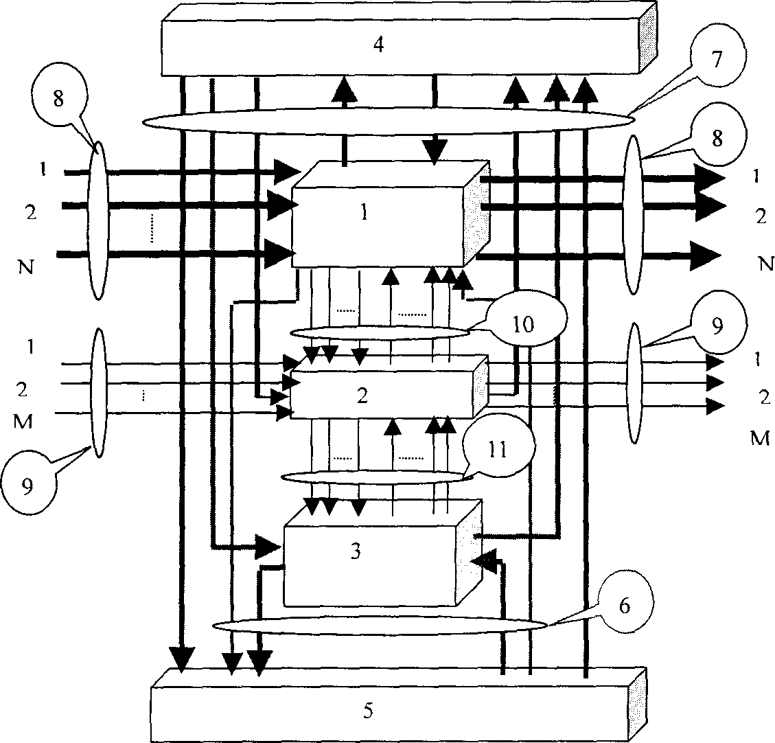
[0037] attached figure 1 It is a functional block diagram of the present invention.

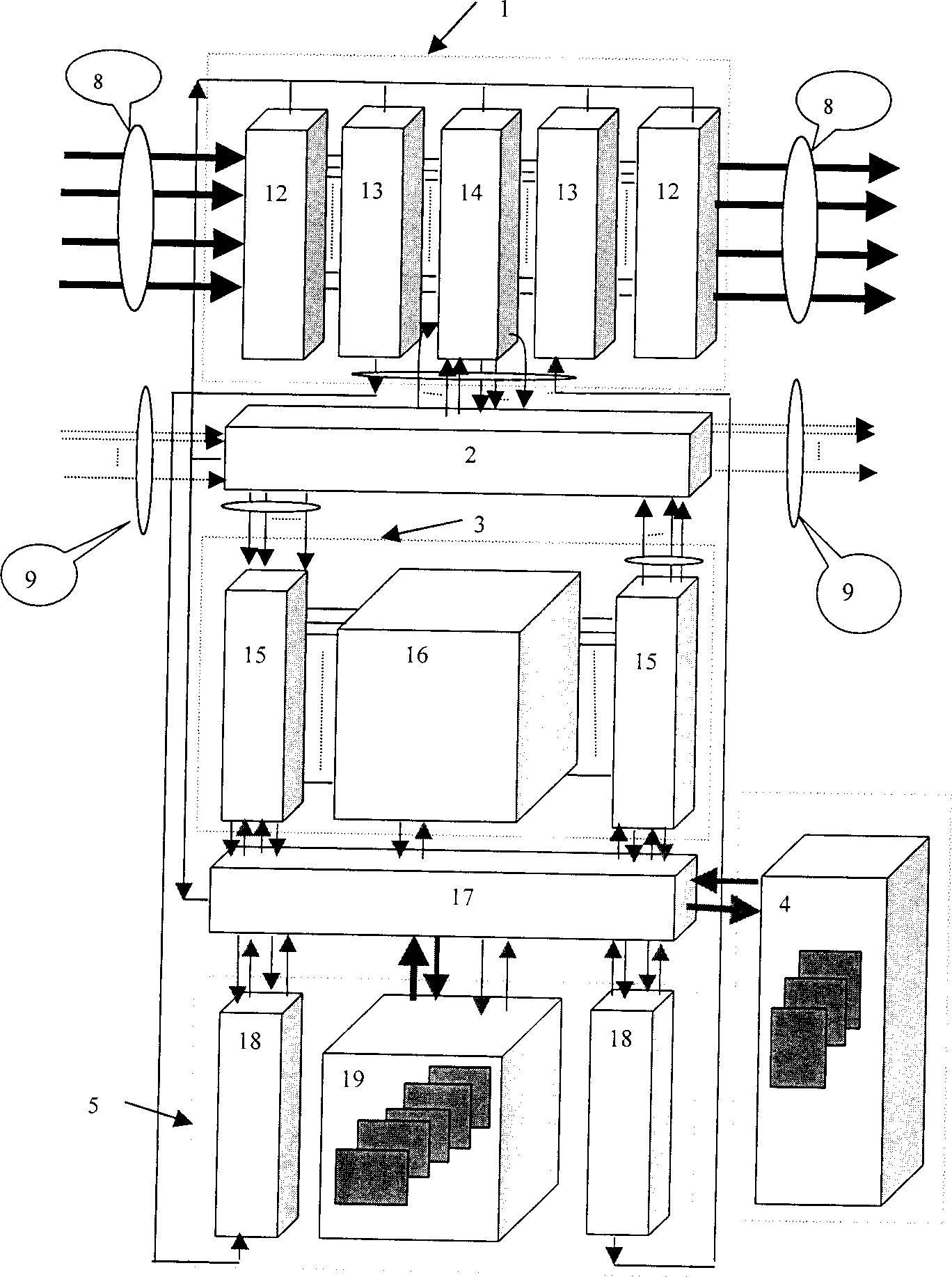
[0038] Such as figure 1 As shown, the present invention includes five main functional units and six interfaces comprising internal and external interfaces: wavelength switching unit (1); optical adaptation unit (2); packet switching unit (3); unified management plane unit (4 ); unified control plane unit (5); control plane interface (6); management plane interface (7); external group road interface (WDM) (8); external branch road interface (9); internal wavelength interface (10); Internal optical fiber interface (11), etc.

[0039] The wavelength switching unit (1) is connected to the WDM optical group signal through the external group interface (8), and at the same time connected to the optical adaptat...


PUM


Abstract

An integrated intelligent photoelectric mixed router applies a distributed modular software and harware system composed of fine functional units and six interfaces. The wane length exchange unit willfinished the business at the big grain wane length degree without delaing with the bypan IP buinsess one by one and the packet exchange unit will finished the IP packet line speed forward and together with the wave length exchange unit will finish controt by SNMP-CORBA unified network manage plane unit and GMPLS technological unified control plane unit. This invention will satify the desine of organizing IP voer WDM optical internet functions of the next generation to reduce the network layers, on hancing the avalability and reduce the setting up of broadband network to maintain the cost.

Description

Technical field: [0001] The present invention relates to a large-capacity integrated intelligent photoelectric hybrid router (referred to as optical router) with a new system structure, which combines the technical advantages of traditional electrical routers and optical wavelength routers to solve the problem of the next-generation optical Internet (IP OverWDM network) on the core nodes of the network. The large capacity of equipment (over Tbits), intelligence (control plane based on Generalized Multi-Protocol Label Switching (GMPLS) technology), robustness and requirements for ensuring multi-service Quality of Service (QoS) belong to the field of broadband network technology. Background technique: [0002] The infrastructure of the Next Generation Internet (NGI) will evolve from the current electric-dominated four-layer network to the optical-dominated IPOver WDM network (called optical Internet), and the flattening trend of the backbone network will become more and more ob...

Claims


Application Information

Patent Timeline
IPC IPC(8): H04J14/08H04Q3/52
Inventor 魏威曾庆济欧阳勇
Owner SHANGHAI JIAO TONG UNIV
Learn More