Pulse intelligent radio-frequency modulation controller

A technique of modulating signal and modulating waveform, which is applied in the field of power generators that output waveforms, and can solve problems that have not yet been proven and are difficult to achieve

Inactive Publication Date: 2002-11-20
MKS INSTR INC
View PDF0 Cites 7 Cited by
  • Summary
  • Abstract
  • Description
  • Claims
  • Application Information

AI Technical Summary

Problems solved by technology

The inability to track rising and falling edges at the same time limits this control technique to controlling output waveforms where, during the low period of the modulating waveform, the pulse returns to 0
Without the ability to simultaneously track the rising and falling edges, it is usually difficult to control a modulated waveform of any amplitude
Therefore, unless the generator system can tolerate the inaccurate ge

Method used


Image

  • Pulse intelligent radio-frequency modulation controller
  • Pulse intelligent radio-frequency modulation controller
  • Pulse intelligent radio-frequency modulation controller

Examples


Embodiment Construction

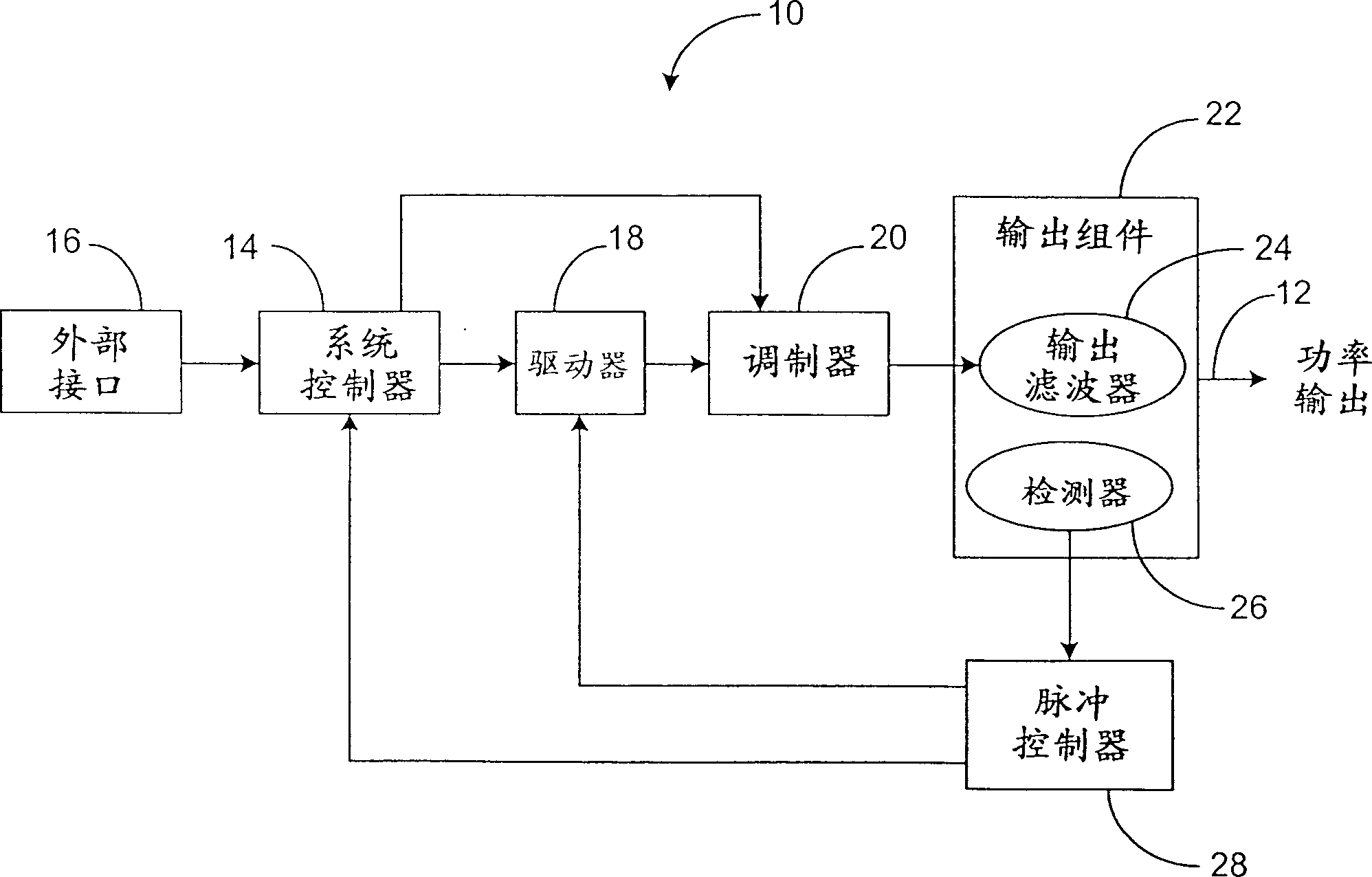
[0017] The following descriptions of preferred embodiments are merely exemplary in nature and in no way limit the invention and its application or uses. see figure 1 , which shows a plasma power generator 10 for providing a power output 12 to a plasma processing system (not shown). It is within the scope of the present invention to provide a power output 12 where the characteristic parameters controlled may be output voltage, output current, output forward power, output reflected power, and output energy. The plasma power generator 10 includes a system controller 14 for generating control signals and processing monitoring and fault signals. The external interface 16 is connected to the system controller 14 through an interface bus, and is used for exchanging information with external devices and users. A driver 18 connected to the system controller 14 generates buffered drive signals corresponding to the respective control signals. The drive signal drives a modulator 20 whi...


PUM


Abstract

The present invention provides a method for controlling the output of a generator. This output provides an output signal with settling time to an impedance load. The settling time of the output signal is determined. The output signal is amplitude modulated with the modulating waveform. A sense signal representing the modulated output signal is generated. The sensing signal is sampled with a sampling time determined based on the settling time of the output signal. A digital representation of the sampled sensor signal is formed. Amplitude modulation of the output is controlled based on the digital representation of the sampled sense signal.

Description

technical field [0001] This invention relates generally to generators providing a power output, and more particularly to power generators providing a modulated output waveform. Background technique [0002] Generators that provide a modulated output are limited in several ways by the waveform sensing / control technology used to control the output. Typically, conventional generators use a control method that tracks the rising edge of a sense signal representing the output waveform. A charge-discharge-hold circuit (CDH circuit) is used to track the rising edge of the sensing signal. The CDH circuit continues to track the waveform until the value of the sensed signal is measured after a predetermined time equivalent to the settling time of the device. A holdover circuit is activated at the same time that the output modulation is disabled, providing an effective continuous DC output independent of the modulation parameters. By multiplying the measured parameter by the duty cyc...

Claims


Application Information

Patent Timeline
IPC IPC(8): H05H1/24G05B19/00H01J37/32H03C1/00H03C1/36H05H1/46
CPCH01J37/32082H01J37/32146H01J37/32174H03C1/36H05H1/46H02M1/0012G05B19/00
Inventor 凯文·P·纳斯曼小丹尼尔·J·沃纳艾伦·T·拉多姆斯基小威廉姆·R·普哈姆斯
Owner MKS INSTR INC
Why Eureka
Try Eureka