Heat control system

A thermal control and thermal connection technology, applied in indirect heat exchangers, heat exchange equipment, household refrigeration equipment, etc., to achieve good working performance

Inactive Publication Date: 2003-01-22
SILMA
View PDF0 Cites 8 Cited by
  • Summary
  • Abstract
  • Description
  • Claims
  • Application Information

AI Technical Summary

Problems solved by technology

The above problems are exacerbated when the electronic equipment it

Method used


Image

  • Heat control system
  • Heat control system
  • Heat control system

Examples


Example Embodiment

[0036] The following is a detailed description of the preferred embodiment.

[0037] The description of the preferred embodiment should be read in conjunction with the accompanying drawings, which should be part of the entire written description of the present invention. In the specification, related words such as "horizontal", "vertical", "upper", "lower", "top", "bottom" and their derivatives. (Such as "horizontally", "upwardly", "downwardly", etc.), should be interpreted as the directions shown in the drawings or drawings discussed at that time. These related words are for the convenience of explanation and usually do not require a specific direction. Terms including "inward" and "outward", "longitudinal" and "horizontal" shall be interpreted as mutual relationship or relative relationship with extension axis, rotation axis or center of rotation as appropriate. The term "communicating" refers to interconnected structures or actions.

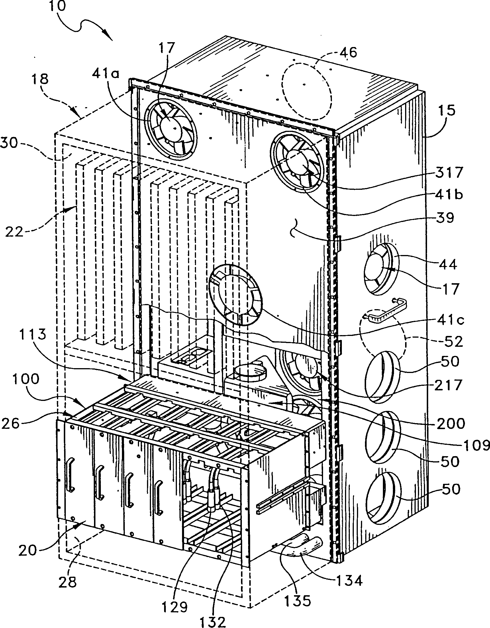
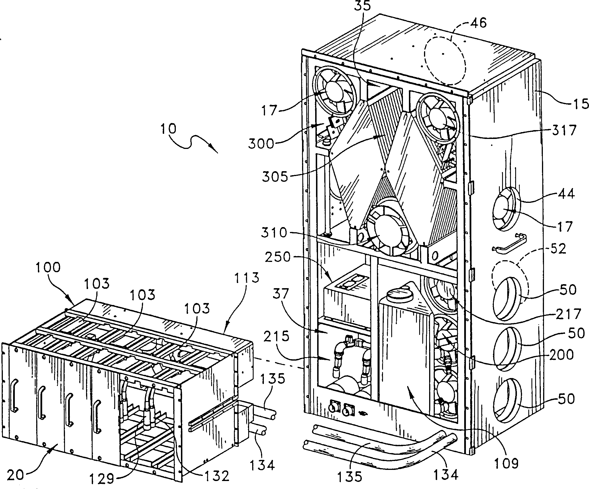
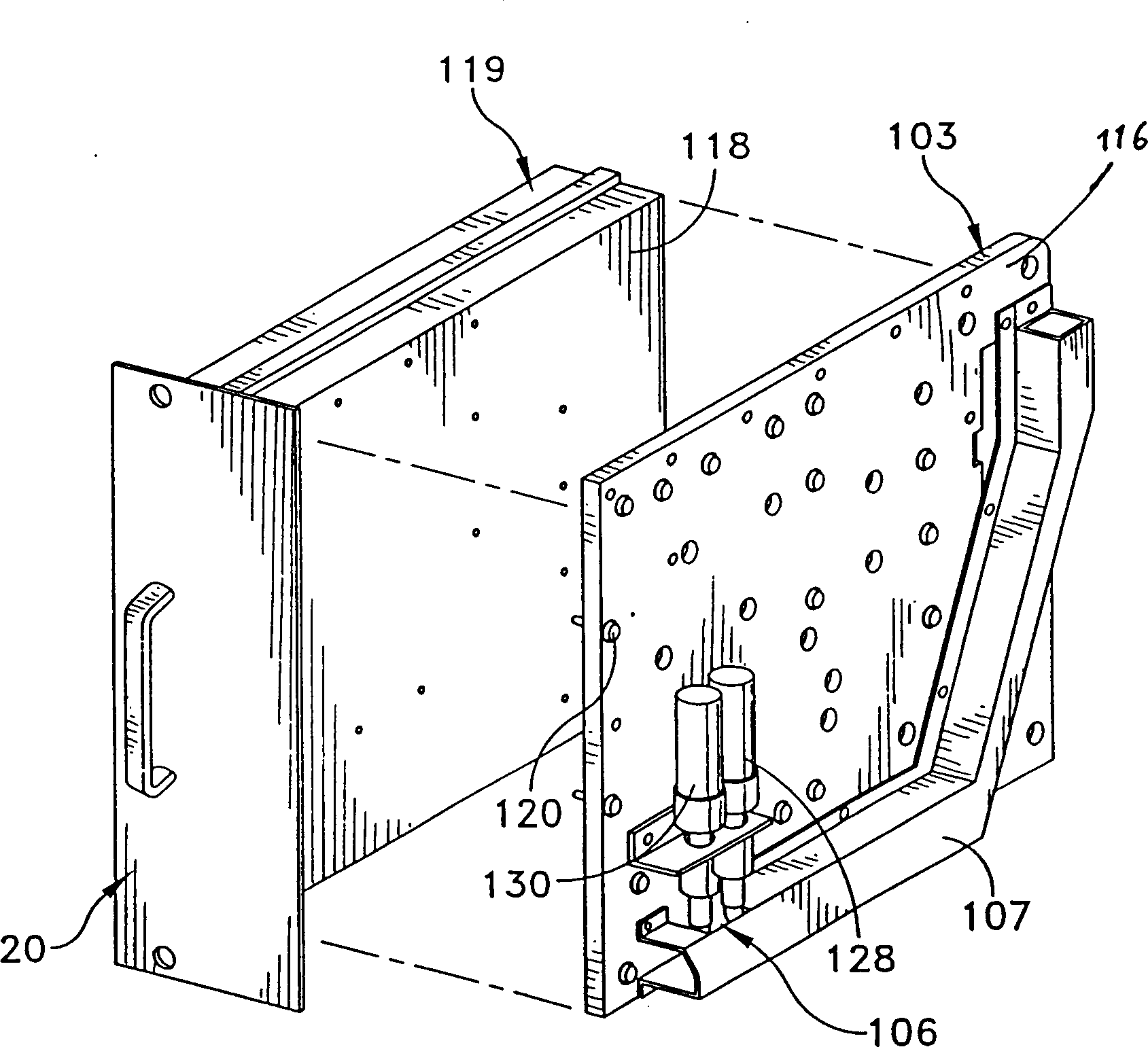
[0038] Refer to figure 1 with figure 2 Th...


PUM


Abstract

The present invention provides a heat management system for controlling the temperature inside of an electronics cabinet. A first heat exchanger is provided that includes a cold plate that is thermally interconnected with the electronic systems and components in the cabinet. A channel is defined in the cold plate that supports a tube having an entrance opening, an exit opening, and is arranged in thermal communication with the electronic systems so as to form a passageway for a liquid coolant fluid to travel through the channel. A second heat exchanger is provided that includes a condenser arranged in fluid flow communication with the entrance opening and the exit opening of the channel and a plurality of fans arranged in confronting relation to the condenser. A third heat exchanger is provided that includes two stacks of substantially parallel plates arranged in two-plate assemblies. Each two-plate assembly has a closed end and an open end such that a closed end of one two-plate assembly is sandwiched between an open end of two adjacent two-plate assemblies. Two fans are provided, one fan arranged so as to blow air onto a portion of the electronics and another fan arranged so as to draw heated air away from the electronics and blow the heated air into the open ends of the two-plate assemblies and the other fan arranged to circulate air from outside the cabinet through the third heat exchanger. The present invention effectively controls the heat distribution of electronic equipment and assembly inside the electronics cabinet.

Description

technical field [0001] The present invention relates to a mechanism and system for improving thermal control of electronic equipment, and more particularly to a hybrid heat exchange system in which three heat exchange components work together to control the heat distribution of electronic equipment. Background technique [0002] The performance of electronic devices is limited by temperature. The performance of semiconductor devices degrades when the internal temperature reaches or exceeds certain limits. For example, in a silicon integrated circuit device, the operating life of the device is cut in half for every 10°C increase in the junction temperature. OEM demands for small package sizes and high device densities make high power densities and the associated efficient heat dissipation very important. [0003] This industrial need is more complicated in the next generation of highly integrated semiconductor devices that generate higher heat energy. These devices are fre...

Claims


Application Information

Patent Timeline
IPC IPC(8): F25D1/00F28D15/02F28F1/22F28F1/32H05K7/20
CPCF28F1/32H05K7/20609F28D15/0266F28F1/22F28F2275/12F25D1/00
Inventor 爱立克L·马力特W·约翰比尔斯基马歇尔D·尼斯利
Owner SILMA
Why Eureka
Try Eureka