Pressurization fluid pipeline

A technology for pressurizing fluids and pipes, applied in the direction of pipes, hoses, rigid pipes, etc., can solve the problems of expensive manufacturing, complex multi-layer pipes, etc., and achieve the effects of material saving, cost reduction, and effective vibration

Inactive Publication Date: 2003-02-12
DSM IP ASSETS BV
View PDF3 Cites 0 Cited by
  • Summary
  • Abstract
  • Description
  • Claims
  • Application Information

AI Technical Summary

Problems solved by technology

[0004] However, a disadvantage of the pressurized fluid conduit disclosed in JP2000-08

Method used


Image

  • Pressurization fluid pipeline
  • Pressurization fluid pipeline
  • Pressurization fluid pipeline

Examples


Embodiment Construction

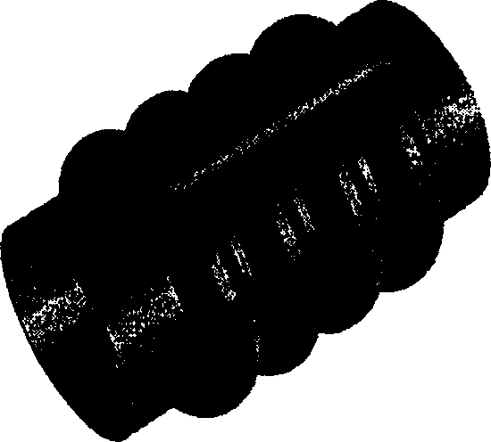
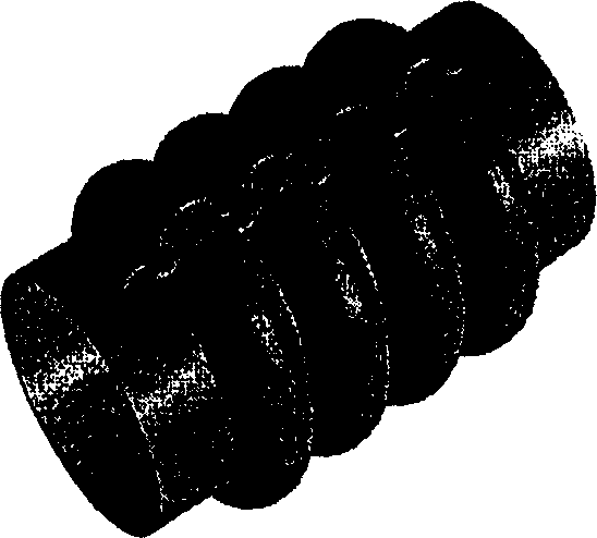
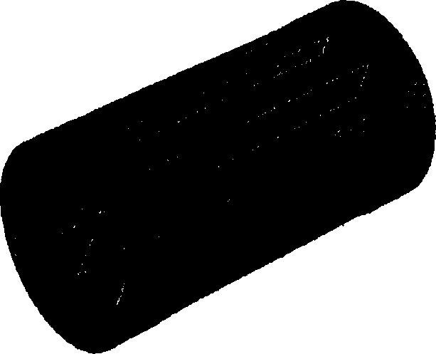
[0026]In a particularly preferred embodiment, the pressurized fluid duct according to the invention is an air duct of an automobile, for example comprising: a first tubular pipe part, i.e. a part with a pipe wall geometry affecting deflection, such as a corrugated part; Two tubular parts, because special thermoplastic material can have good performance of air duct at both lower and higher service temperature. The corrugated portion of the air duct preferably has corrugations of a geometry that substantially resists longitudinal elongation of the duct when operated at elevated operating temperatures and pressures.

[0027] In a preferred embodiment according to the invention, the thermoplastic material within the pressurized fluid conduit is a thermoplastic block copolyester elastomer, preferably consisting of block copolyetherester elastomer.

[0028] Blocky copolyethers contain soft blocks of elastomeric polymers and hard blocks of semi-crystalline polyester. Block polymer o...


PUM

PropertyMeasurementUnit
Modulusaaaaaaaaaa
Modulusaaaaaaaaaa
Shore hardnessaaaaaaaaaa

Abstract

The invention relates to a pressurized fluid conduit made from a semi-crystalline thermoplastic material that has a hardness of between 50 and 65 Shore D and a modulus at 150 DEG C of at least 60 MPa. Advantages of such a conduit are easy handling and assembling at for example room temperature, while still requirements regarding burst-pressure and deformation at elevated operating temperatures are fulfilled. Other important advantages include significant savings in material use and better vibration and noise damping. The invention also concerns use of a semi-crystalline thermoplastic material with a hardness of between 50 and 65 Shore D and a modulus at 150 DEG C of at least 60 MPa for making a pressurized fluid conduit via an extrusion moulding process, and a process for making said conduit.

Description

【Technical field】 [0001] The present invention relates to a pressurized fluid conduit. The invention also relates to the use of semi-crystalline thermoplastic materials with specific properties for the manufacture of single-layer pressurized fluid pipes by means of extrusion and the method of making said pipes. 【Background technique】 [0002] Such pressurized fluid conduits are known, inter alia, from JP2000-088151A. In this patent application a multilayer tubular shaped article is described comprising an inner layer consisting of a semi-crystalline ester-based elastomer (I) having a Shore hardness of between 50-70 and having a Shore hardness of The outer layer is composed of semi-crystalline ester-based elastomer (II) between 30-50. The elastomer (II) is a block-like interpolymer comprising hard blocks of semi-crystalline polyester and soft blocks of polypolyether, the blocks being connected to each other by a urethane binder. [0003] In this application, it is understo...

Claims


Application Information

Patent Timeline
IPC IPC(8): F16L11/06B29C49/04B29K67/00B29L23/00B29L31/30B32B1/08F16L9/12F16L11/00F16L11/04F16L11/11
CPCB32B1/08Y10S138/07F16L9/12F16L11/04F16L11/111F16L11/15Y10T428/1397F16L11/00
Inventor J·科南
Owner DSM IP ASSETS BV
Why Eureka
Try Eureka