Device for reducing pressure pulsations in hydraulic manifolds
A pressure pulsation, pressure technology, applied in the direction of pipe elements, fluid flow, springs/shock absorbers, etc., can solve problems such as high cost
- Summary
- Abstract
- Description
- Claims
- Application Information
AI Technical Summary
Problems solved by technology
Method used
Image

Examples
Embodiment Construction
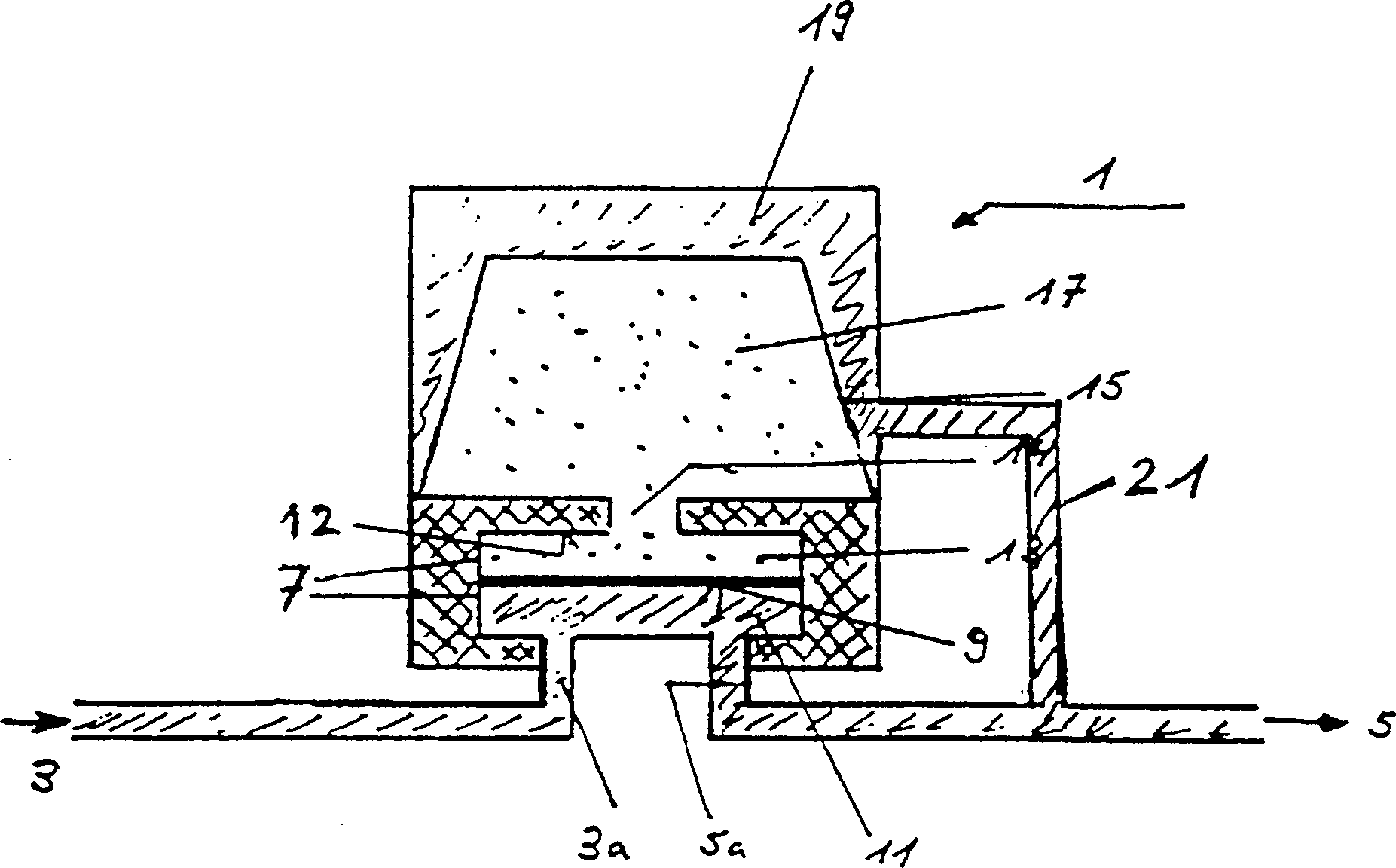
[0026] figure 1 A cross-section of a passive pulsation damper according to the invention, which is suitable, for example, for installation in a hydraulic line system of a power steering of a motor vehicle is shown in simplified outline. according to figure 1 The pulsation damper of the present invention is connected to the hydraulic line either between the input port 3 and the output port 5 or in a branch of the hydraulic line such that the line is connected to the pulsation damper via the connecting line 3a or 5a. The connecting line 3a or 5a leads to a balance chamber 7 which is divided into a hydraulic balance chamber 13 by a membrane 9 , such as a metal membrane, an elastic body or a movable wall.
[0027] The pressure balance chamber 13 is connected with the gas chamber 17 in the energy storage membrane 15 through the through hole 14 . The gas chamber 17 and the energy storage membrane 15 form a so-called gas spring. Of course, mechanical springs or other spring elemen...
PUM
 Abstract
Description
Claims
Application Information