Electromagnetic flow meter

An electromagnetic flowmeter and flow signal technology, which is applied in the application of electromagnetic flowmeters to detect fluid flow, volume/mass flow generated by electromagnetic effects, and measurement flow/mass flow. flow meter etc.

Inactive Publication Date: 2003-04-09
YOKOGAWA ELECTRIC CORP
View PDF2 Cites 23 Cited by
  • Summary
  • Abstract
  • Description
  • Claims
  • Application Information

AI Technical Summary

Problems solved by technology

However, in some cases, soil and gravel sewage are mixed in the wastewater, but the electromagnetic flowmeter cannot be used to monitor the soil and gravel sewage

Method used


Image

  • Electromagnetic flow meter
  • Electromagnetic flow meter
  • Electromagnetic flow meter

Examples


no. 1 example

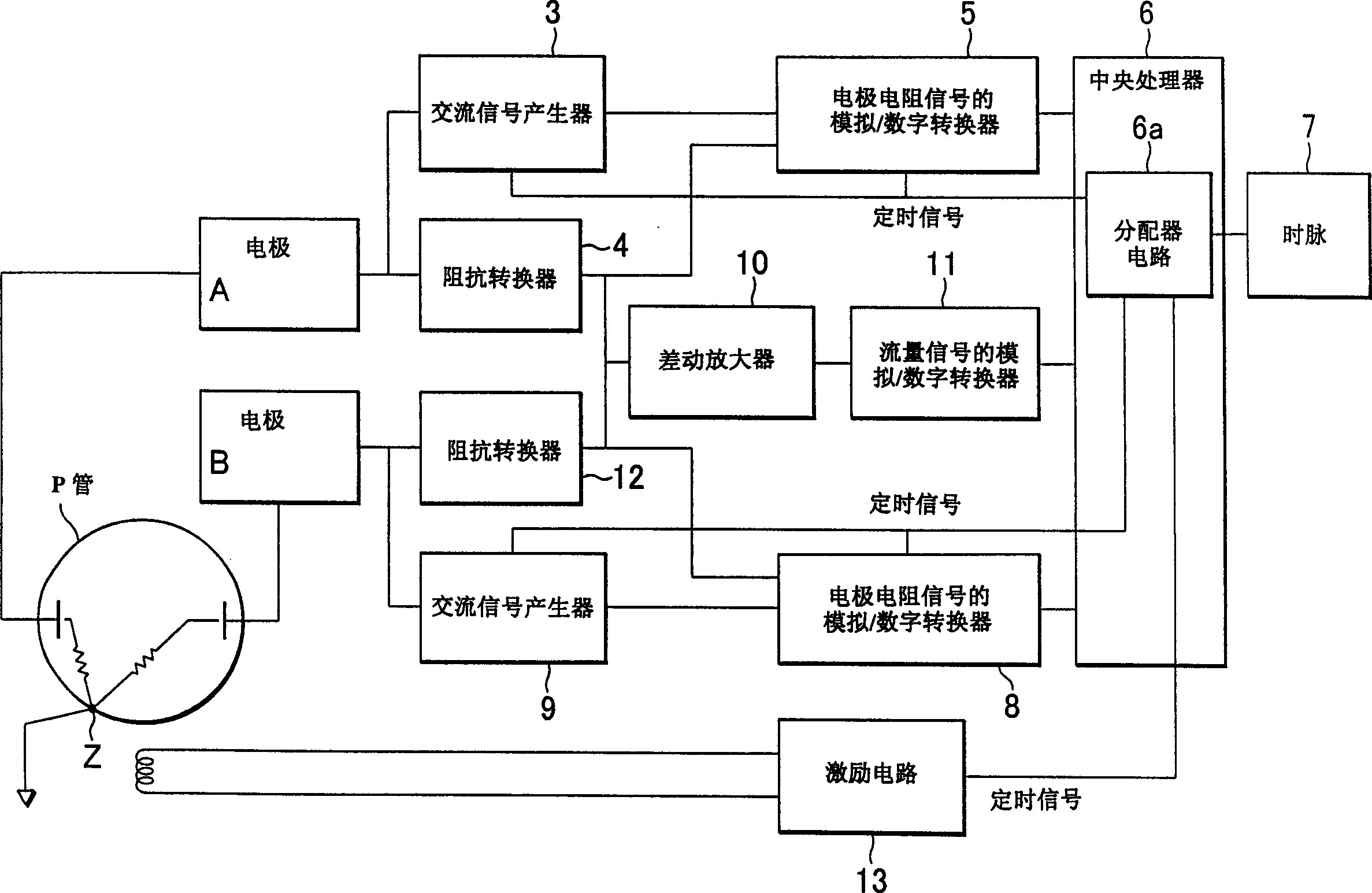
[0100] figure 1 is a block diagram of the first embodiment of the present invention.

[0101] Such as figure 1 As shown, AC signal generators 3 and 9 for generating AC signals (diagnostic signals) are connected to electrodes (detection electrodes, hereinafter simply referred to as "electrodes") A and B as diagnostic signal generators to generate diagnostic signals, and Impedance converters 4 and 12 are also connected to electrodes A and B. The analog / digital converters 5 and 8 of the electrode resistance signals connected to the AC signal generators 3 and 9 are used for synchronous detection and analog / digital conversion of the diagnostic signals generated at the electrodes A and B. The distributor circuit 6 a is used for distributing the clock signal 7 provided by the CPU 6 . The timing signal from the distributor circuit 6 a is thus output to the AC signal generators 3 and 9 and the driving circuit 13 .

[0102] In addition, the timing signal from the divider circuit 6a ...

no. 2 example

[0151] Figure 12 and Figure 13 It is a block diagram of the second embodiment of the present invention. Figure 13 yes Figure 12 A modified example of the system shown. Figure 14 is the temporal diagram of the above diagram. At Figure 12 and Figure 13 The structure shown, for the figure 1 Identical boxes are given the same reference numbers. In addition, at Figure 12 and Figure 13 , because the pipe P connected to the electrodes A and B and the ground electrode Z also have the same figure 1 same structure, so their description will be omitted.

[0152] At Figure 12 In the block diagram, the clock of the diagnosis circuit and the clock of the flow signal detection circuit are separated from each other (clock 1 and clock 2). In other words, each clock signal (clock 1 and clock 2 ) is distributed by two divider circuits 16 and 18 . This is also possible by choosing a timing frequency that is a non-integer multiple of the excitation frequency when a clock ass...

no. 3 example

[0157] Next, diagnostic signal sampling for single-frequency excitation and dual-frequency excitation will be described.

[0158] The above-mentioned first embodiment and the second embodiment are all embodiments of single-frequency excitation, and the signal waveforms detected by the electrodes A and B in the diagnostic operation include such as Figure 15 The diagnostic signal component and the differential noise component are shown. Therefore, design the diagnostic signal frequency to be four times or more the excitation frequency, such as Figure 15 As shown, and in order to reduce the influence of differential noise, the diagnostic signal is sampled in the second half of the excitation current waveform with less differential noise.

[0159] Next, the mode of measuring conductivity will be explained. In the first embodiment of the present invention Figure 10 The frequencies on the boundaries of the linear region A and the circular region B of the Cole-Cole diagram show...


PUM


Abstract

The present invention is intended to achieve measurement of electrode impedance that is not easily affected by fluid noise, and to accurately detect adhesion and discriminate the type of fluid. An electromagnetic flowmeter that is provided with a pipe through which the fluid to be measured is passed, applies a magnetic field to the above fluid driving the excitation coils using the excitation circuit, and thereby measures the flow rate of the fluid passing through the above-mentioned pipe; further comprising: a pair of detecting electrodes that detect the flow signal corresponding to the flow rate of the fluid passing through the above-described pipe, an earth electrode whose potential becomes the reference potential when the flow rate is measured, diagnosing signal generators that apply the diagnosing signals between the above detecting electrodes and the above earth electrode, and a diagnosis circuit to detect the resistance values between the above detecting electrodes and the above earth electrode as diagnostic signals.

Description

technical field [0001] The present invention relates to an electromagnetic flowmeter for measuring the flow rate of a conductive fluid or the like, and in particular to an electromagnetic flowmeter that performs empty pipe detection, that is, regardless of whether the pipe is filled with fluid or not, and also detects An electromagnetic flowmeter that measures the presence or absence of an insulating substance on an electrode and measures the electrical conductivity of the fluid to be measured (hereinafter simply referred to as "conductivity"). Background technique [0002] As a well-known electromagnetic flowmeter for implementing empty pipe detection, Japanese Patent No. 2880830 discloses a structure for performing empty pipe detection by applying an AC voltage having a frequency that is an even fraction of the excitation frequency to a circuit for detecting electrodes in the pipe . Furthermore, Japanese National Patent Application Publication No. 9-502267 (1997) disclose...

Claims


Application Information

Patent Timeline
Patent Type & Authority Applications(China)
IPC IPC(8): G01F1/58G01F1/60
CPCG01F1/588G01F1/60G01F25/10
Inventor 石川郁光太田博信
Owner YOKOGAWA ELECTRIC CORP
Why Eureka
Try Eureka