Broad-band light source signal detection method and its detector

A broadband light source and signal detection technology, which is applied in the direction of instruments, measuring devices, scientific instruments, etc., can solve the problems of increased sensor cost, complex structure, and lack of distributed monitoring functions for signals to be detected, and achieves low product prices and extended length The effect of simple range and overall structure

Inactive Publication Date: 2003-04-23
TIANJIN UNIV
View PDF2 Cites 27 Cited by
  • Summary
  • Abstract
  • Description
  • Claims
  • Application Information

AI Technical Summary

Problems solved by technology

[0003] U.S. Patent No. US5555086 discloses a separate optical fiber sensor using phase modulation technology to detect the relative strength of the optical signal coupled at each point when the broadband light source is transmitted in the optical fiber, but its structure is complex, modulation and demodulation and related Signal processing can significantly increase the cost of the sensor
[0004] U.S. Patent No. US5094534 also discloses a total reflection structure and a coherent selective optical fiber sensor to detect the relative intensity of the optical signal coupled at each point when the broadband light source is transmitted in the optical fiber, but it does not have the ability to detect the signal Distributed monitoring function

Method used


Image

  • Broad-band light source signal detection method and its detector
  • Broad-band light source signal detection method and its detector

Examples


Embodiment Construction

[0034] Below in conjunction with accompanying drawing, the implementation of the present invention is described in detail as follows:

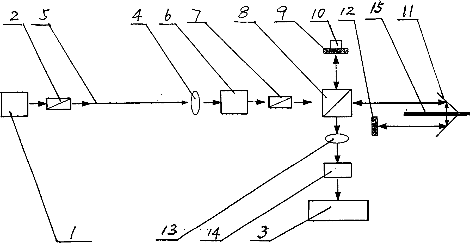
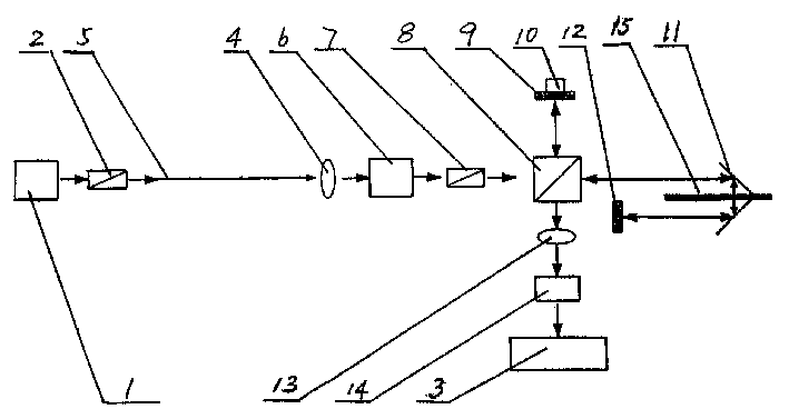
[0035] exist figure 1 Among them, a detector of a broadband light source signal detection method, comprising:

[0036] 1. The detection light source system is composed of a broadband light source 1 and a polarizer A2, which is used to convert the broadband light source into detectable linearly polarized light;

[0037] 2. Polarization-maintaining optical fiber 5, which is used to lay on the object to be measured, and transmit the linearly polarized light output by the detection light source system to the polarized light splitting system;

[0038] 3. The polarization beam splitting system is composed of a beam expander lens 4, a λ / 2 wave plate 6, a polarizer B7, and a polarization beam splitter prism 8, and is used to reflect the linearly polarized light output by the polarization-maintaining fiber 5 into the Michelson interferometer, and tra...


PUM


Abstract

The method for detecting wideband light source signal includes the following steps: 1. laying the polarization-protecting optical fibre on the tested body; 2. one end of the polarization-protecting optical fibre is inputted into wideband detection light source; 3. using polarizing spectroscopic system to divide the wideband detection light source outputted by another end of the polarization-protecting optical fibre into linear polarized light, reflecting and transmission, feeding the linear polarized light into Michelson interferometer; and 4. making the interference light signal undergo the processes of collection, photoelectric conversion, A / D conversion, etc. to output the detection parameters of said tested body. Said invented detector is formed from detection light source system.

Description

technical field [0001] The invention belongs to the category of optical measuring instruments, in particular to an instrument for broadband light source transmission detection. Background technique [0002] At present, in the transmission of broadband light sources, when linearly polarized light is incident along a characteristic axis (fast axis or slow axis) of a polarization-maintaining fiber, the optical signal will propagate along this axis and will not be coupled to another characteristic axis. Due to the influence of environmental factors, such as pressure, tension, torsion, temperature and other factors, the optical signal will be coupled from one characteristic axis to another characteristic axis. Therefore, by detecting the relative intensity of the optical signal coupled at each point in the optical fiber, it can be used to detect the force on the point or the change of the ambient temperature. [0003] U.S. Patent No. US5555086...

Claims


Application Information

Patent Timeline
Patent Type & Authority Applications(China)
IPC IPC(8): G01D5/353G01N21/17G01N21/21G01N21/41
Inventor 井文才张以谟周革刘铁根李海峰贾大功
Owner TIANJIN UNIV
Why Eureka
Try Eureka