Method for maintaining position of thin belt

A transmission belt, thin-shaped technology, applied in the field of mechanical deviation correction, can solve problems such as cracking, deformation of the side of the transmission belt, etc.

Inactive Publication Date: 2003-04-30
BEIJING INSTITUTE OF CLOTHING TECHNOLOGY
View PDF0 Cites 12 Cited by
  • Summary
  • Abstract
  • Description
  • Claims
  • Application Information

AI Technical Summary

Problems solved by technology

The traditional correction method will deform the side of this type of drive belt, or even crack

Method used


Image

  • Method for maintaining position of thin belt
  • Method for maintaining position of thin belt
  • Method for maintaining position of thin belt

Examples


Embodiment Construction

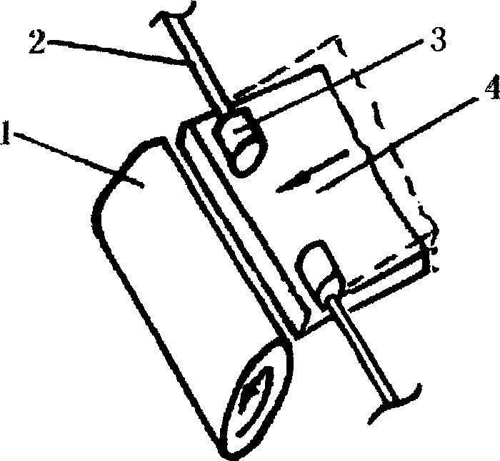
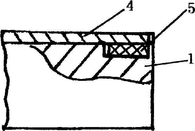
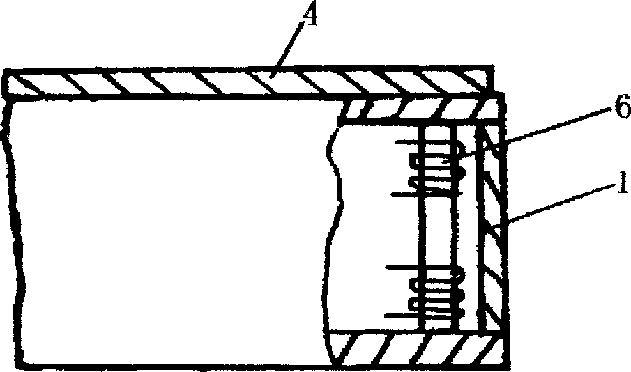
[0012] The invention is a deviation correcting method for a thin transmission belt. The thin-shaped transmission belt moves under the drive of the transmission roller, and deviation phenomenon will inevitably occur during the movement process, thus affecting the normal production. Using magnetic force correction and grinding pressure correction can reduce or prevent deviation. Magnetic correction is divided into two types: permanent magnet and electromagnetic. Be explained below in conjunction with accompanying drawing:

[0013] figure 1 It is a schematic diagram of the structure of the grinding pressure correction device. The thermal transfer substrate on the paperless thermal transfer printing and dyeing test machine is 0.2mm thick aluminum foil. Grinding rollers 3 are arranged above the two ends of the two drive rollers 1 at the entrance and exit of the thermal transfer area, respectively. By detecting the deviation speed of the base material and transmitting this info...


PUM


Abstract

An offset correcting method for thin driving belt has two approaches. One approach is used of magnetic attraction, that is, the permanent-magnet material is installed on the driving roller or the electromagnetic coil is installed in the driving roller and magnetic thin driving belt is used. Another approach is to arrange two pressing friction rollers at both ends of driving roller above the driving belt and regulating their pressure and tension can correct the offset of thin driving belt.

Description

technical field [0001] The invention belongs to the category of mechanical deviation correction, in particular to a deviation correction method for thin transmission belts. Background technique [0002] Thin transmission belts are often supported by many transmission rollers on the machine for circular motion. If the processing accuracy of the transmission rollers and the level and parallelism of the installation do not meet the requirements, the transmission belt will run off-track and affect normal production. For example, the paperless thermal transfer printing and dyeing machine uses a thin transmission belt to realize the integration of printing and thermal transfer printing, and completely solves the problems of paper consumption, indirect water consumption and water pollution in the existing thermal transfer printing process. Similar situations also exist Transmission production device for spreading paint, etc. Traditional correction methods will deform or even crack...

Claims


Application Information

Patent Timeline
Patent Type & Authority Applications(China)
IPC IPC(8): B65G15/64B65G39/16B65G54/02
Inventor 王红凤卢向阳沈忠耀杨树藩
Owner BEIJING INSTITUTE OF CLOTHING TECHNOLOGY
Why Eureka
Try Eureka