

Ramp automobile collision experiment system and method
A crash test and ramp technology, applied in the control/adjustment system, vehicle accessories, vehicle components, etc., can solve the problems of difficult acceleration and difficult cost control, and achieve the effect of accurate method and reduced pitching vibration
- Summary
- Abstract
- Description
- Claims
- Application Information
AI Technical Summary
Problems solved by technology
Method used
Image

Examples
Embodiment 1
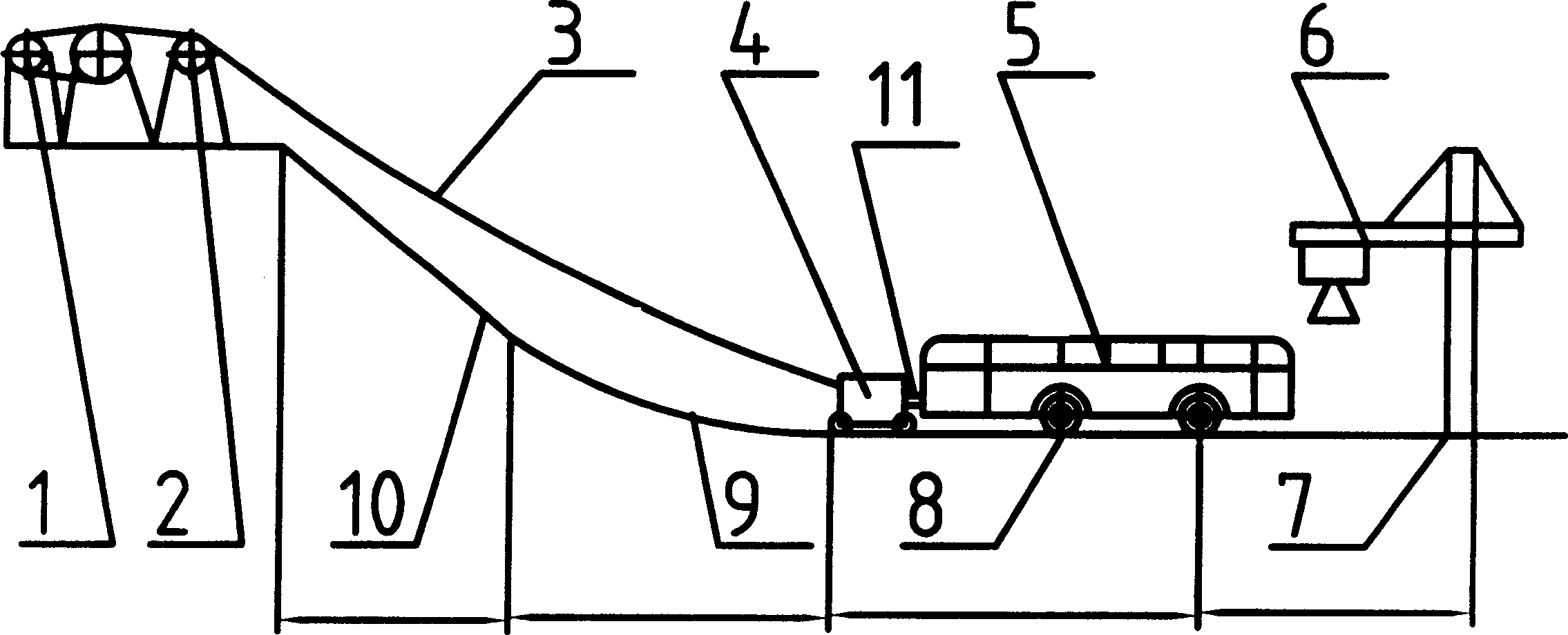
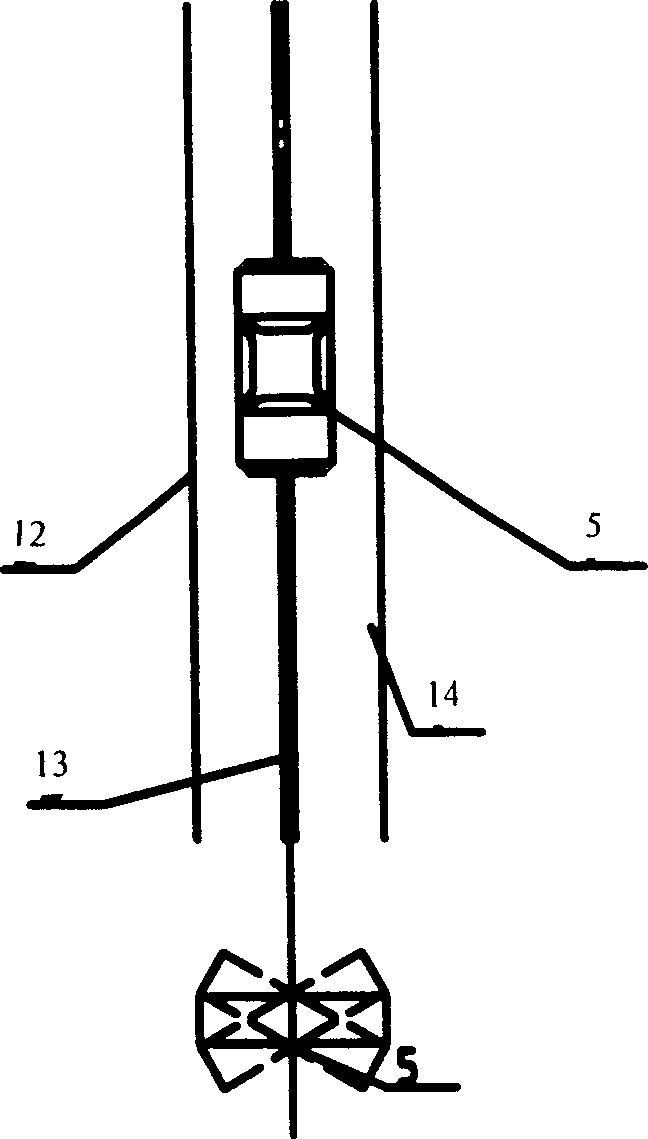
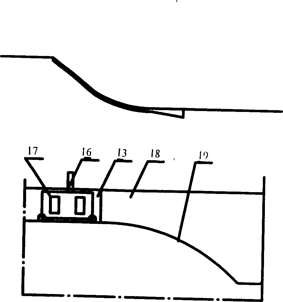
[0034] according to figure 1 , 2, 3, 5, 6 make a ramp-type vehicle collision test system, use plates or stones, and also use anchor rods, concrete cushions and concrete pavement to form an acceleration ramp 14 with a height difference of about 48 meters. The maximum slope Angle is 32 °, and the curvature of ramp 14 curve segments is a quadratic curve. The guiding device adopts rail-type guiding (single-task type), and the guiding track adopts the structure of a rolling roller coaster. Hoist is 10 tons, and traction positioning car 4 is provided with a moving pulley, and the maximum lifting vehicle weight is 20 tons (being provided with two moving pulleys can reach 40 tons); Design top speed is 100 kilometers per hour, and experimental car 5 speeds per hour are 98 kilometers per hour. It has a hoisting and starting system for an experimental vehicle consisting of a hoisting hoist 2, traction wire rope 3, supporting rollers, pulleys and anchoring elements, a traction positioni...
Embodiment 2
[0036] Embodiment 2 (multitasking:)
[0037] according to figure 1 , 4, 5, 6 make a ramp-type vehicle collision test system, the height difference of the ramp is about 48 meters, the maximum slope angle is 32°, and the curvature of the curve section of the ramp is a quadratic curve. The guiding device adopts the remote control guiding system (multi-task type). The winch is 10 tons, and the traction trolley is equipped with a moving pulley, and the maximum hoisting weight is 20 tons (with two moving pulleys, it can reach 40 tons); the design maximum speed is 100 km / h, and the speed of the experimental vehicle is 98 km / h. Figure 4 It is a remote-controlled guiding system, another kind of guiding device; through the remote-controlled guiding system, the test vehicle 5 can collide with different structures 15 along different collision lines 3, which can improve the test efficiency. All the other parts are the same as in Example 1.
Embodiment 3
[0039] The present embodiment applies the ramp type vehicle collision test system that above-mentioned embodiment makes to carry out the method for collision test: (1) during the test, first start the traction device to pull the test car to the corresponding position (certain height) of the ramp; The allowable vehicle speed is lower, therefore, the traction device requires less power. The direction of the traction wire rope is guaranteed by the roller, and the traction positioning vehicle is equipped with a traction hook and a decoupling release mechanism, which is convenient for the connection and separation between the traction wire rope and the experimental vehicle.
[0040] (2) When the test car is pulled to the corresponding position preset on the ramp, the traction wire rope is separated from the test car through the decoupling release mechanism, and the test car will accelerate down under the action of gravity, and the curve transition section ensures that the test car ...
PUM
 Abstract
Description
Claims
Application Information